SECTION 6 OPERATION
169000
42
Revision F
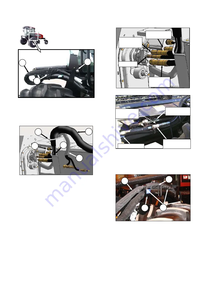
b. Remove the cap (C) from electrical connector,
and remove connector from support bracket.
c. Disengage and rotate lever (D) counterclockwise
to fully up position to release the hose
bundle (E).
d. Move hose/electrical bundle (E) to header.
e. Route bundle (E) from windrower through
support (F) and access hole (G) in header frame
alongside existing hose bundle (H) from header.
f.
Remove cover on header electrical
receptacle (J).
g. Push connector onto receptacle, and turn collar
on connector to lock it in place.
h. Attach cover to mating cover on windrower
wiring harness.
i. Remove caps from hydraulic couplers, and
clean if necessary.
j. Push hose connectors onto mating receptacles
(as shown) until collars on receptacles snap into
lock position.
k. Route auger return and reel pressure hose
bundle (H) from header to windrower, and locate
bundle above existing hose support (K)
(as shown).
l.
Secure with three straps (L), and lower lever (D).
(continued next page)
G
H
J
E
F
D
C
E
H
K
L
D
STANDARD HEADER
KNIFE and
CONDITIONER
PRESSURE
CASE DRAIN
KNIFE and
CONDITIONER
RETURN
REEL and AUGER
PRESSURE
GRASS SEED HEADER
KNIFE PRESSURE
(FEMALE FITTING
AT HEADER)
KNIFE RETURN
(MALE FITTING
AT HEADER)
CASE DRAIN
AUGER and REEL
PRESSURE
Summary of Contents for A30-D
Page 2: ...MACDON A40 D SELF PROPELLED AUGER HEADER MACDON A30 D PULL TYPE MOWER CONDITIONER...
Page 3: ...169000 1 Revision F...
Page 4: ...169000 2 Revision F...
Page 6: ...169000 4 Revision F...
Page 181: ...NOTES 169000 179 Revision F...
Page 182: ......


