215922
314
Revision A
ϭϬϯϴϬϭϱ
A
B
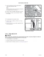
Figure 5.125: DEF Tank Head
–
Top View
14. Insert DEF head (A) into the DEF tank and align the screw
holes with the hose connectors facing the windrower.
15. Secure the DEF head to the tank with six screws (B).
1020201
A
B
C
D
E
F
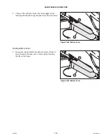
Figure 5.126: DEF Tank Head
16. Connect electrical harness (A).
IMPORTANT:
Correct hose connections to the DEF tank head, DEF supply
module, and aftertreatment system are important.
Improper connections will result in a loss of suction,
causing the engine to derate (lose power).
17. Connect coolant pressure line (C) and coolant return
line (B) to the DEF head.
18. Connect DEF suction line (E) and DEF backflow line (D) to
the DEF head.
19. Connect vent hose (F) to the DEF head.


