262391
160
Revision A
1011164
A
B
C
D
E
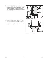
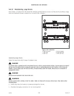
Figure 4.146: Cover Plate and Top Plate
14. Apply a bead of medium-strength threadlocker
(Loctite
®
243 or equivalent) around the threads of M10 hex
flange head bolt (B). Install bolt (B) through cover plate (A)
and top plate (C). Torque the hardware to 61 Nm (45 lbf·ft).
15. Apply a bead of medium-strength threadlocker
(Loctite
®
243 or equivalent) around the threads of M10 hex
flange head bolt (D). Install bolt (D) through cover plate (A)
and vertical shield (E). Torque the hardware to 61 Nm
(45 lbf·ft).
16. Tighten bolts (B) and (D).
1011078
A
B
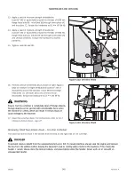
Figure 4.147: Vertical Shield
17. Position vertical driveshield (B) as shown. Apply a bead of
medium-strength threadlocker (Loctite
®
243 or equivalent)
around the threads of four M10 hex flange head bolts (A).
Use bolts (A) to secure the vertical driveshield. Torque the
bolts to 61 Nm (45 lbf·ft).
WARNING
Ensure that the cutterbar is completely clear of foreign objects.
Foreign objects can be ejected with considerable force when
the machine is started, which can result in serious injury or
cause damage to the machine.
18. Close the cutterbar doors. For instructions, refer to
Closing Cutterbar Doors, page 27
Removing Large Non-Driven Drums
The non-driven large drums are held in place with four bolts.
DANGER
To prevent injury or death from the unexpected start-up or fall of a raised machine, always stop the engine and remove
the key from the ignition before leaving the operator
’
s seat or making adjustments to the machine. If the rotary disc
header is raised, always close the lock-out valves, and place blocks under the header. Never work on or beneath an
unsupported header.


