262391
164
Revision A
4.4.13
Replacing Cutterbar Spindle Shear Pin
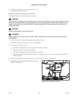
To prevent damage to the cutterbar and drive systems, each disc is attached to a spindle containing a shear pin.
1011409
A
B
Figure 4.153: Cutterbar Spindles
If the disc contacts a large object such as a stone or stump,
pin (A) will shear and the disc will stop rotating and move
upwards. The presence of snap ring (B) ensures that the disc will
remain attached to the spindle.
IMPORTANT:
•
Ensure that the slots on both shear pins (A) are aligned
horizontally.
•
Spindles that rotate clockwise have right-leading threading.
•
Spindles that rotate counterclockwise have left-leading
threading.
NOTE:
Once the spindle has risen due to the failure of the shear pin, the
spindle
’
s bearing will become unloaded. The spindle will appear
to be damaged. Do
NOT
replace the spindle simply because it
has excessive play. Check the play of the spindle
AFTER
torquing
the spindle nut and replacing the damaged shear pin.
Removing Cutterbar Spindle Shear Pin
Once the shear pin on a cutterbar spindle has broken, it will need to be removed.
DANGER
To prevent injury or death from the unexpected start-up or fall of a raised machine, always stop the engine and remove
the key from the ignition before leaving the operator
’
s seat or making adjustments to the machine. If the rotary disc
header is raised, always close the lock-out valves, and place blocks under the header. Never work on or beneath an
unsupported header.
DANGER
Ensure that all bystanders have cleared the area.
WARNING
Exercise caution when working around the blades. Blades are sharp and can cause serious injury. Wear gloves when
handling blades.
1.
Position the rotary disc header at an appropriate height for the task.
2.
Shut down the engine, and remove the key from the ignition.


