background image

262391

41

Revision A

3.13

Operating Rotary Disc Header

Operating the rotary disc header properly, results in less crop lost and increased productivity during harvest. This includes
making proper adjustments while operating the machine to suit various crops and harvest conditions. Regular maintenance
and operating the machine safely and properly increases the machine

s length of service.

The variables listed in Table

3.2, page 41

and detailed on the following pages will affect the performance of your rotary

disc header. You will quickly become adept at adjusting your machine to produce the desired results. Although most of the
adjustments have been set at the factory, settings can be changed to suit your crop conditions.

Table 3.2 Rotary Disc Header Performance Variables

Variable

Refer to

Float

3.13.2 Float, page 43

Cutterbar angle

3.13.4 Cutterbar Angle, page 48

Cutting height

3.13.3 Cutting Height, page 46

Ground speed

3.13.5 Ground Speed, page 49

Conditioning: roll type

3.14 Roll Conditioner, page 55

3.13.1

Raising and Lowering Rotary Disc Header

The rotary disc header can be raised or lowered to clear obstacles, for maintenance, or for storage and transport.

Header Raise / Lower

Auxiliary Lift System

The auxiliary lift system uses position sensors, an electronically controlled valve, and hydraulic cylinders to automatically
adjust the header position when the Operator adjusts header raise/lower position with the 3-point hitch.

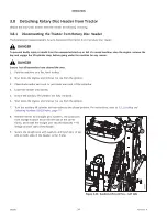
DANGER

To prevent bodily injury or death from the unexpected start-up or fall of a raised machine, stop the engine, remove the
key from the ignition, and engage the lift cylinder lock-out valves before going under the machine.

DANGER

Ensure that all bystanders have cleared the area.

OPERATION

Summary of Contents for R1 FR Series

Page 1: ...R1 FR Series Front Mount Rotary Disc Operator s Manual 262391 Revision A Original Instruction The Harvesting Specialists...

Page 2: ...sed on the information available and in effect at the time of printing MacDon Industries Ltd makes no representation or warranty of any kind whether expressed or implied with respect to the informatio...

Page 3: ...r use the machine Use this manual as your first source of information about the machine If you follow the instructions provided in this manual and use MacDon parts when repair is necessary the rotary...

Page 4: ...anual Storage Case Store the operator s manual and the parts catalog in the plastic manual case A at the right side of the rotary disc header This document is currently available in English 262391 ii...

Page 5: ...f the header the carrier frame in the spaces provided below the hitch and the transport option if equipped provided below 1015306 A Rotary Disc Header Serial Number Location Rotary disc header serial...

Page 6: ......

Page 7: ...xiliary Lift Cylinder Lock Out Valves 22 3 2 1 Locking and Unlocking Auxiliary Lift Cylinders 22 3 3 Driveshields 23 3 3 1 Opening Driveshields 23 3 3 2 Closing Driveshields 24 3 4 Cutterbar Doors 26...

Page 8: ...Gap 55 Adjusting Roll Gap Steel Rolls 56 3 14 2 Roll Tension 57 Adjusting Roll Tension 57 3 14 3 Roll Timing 58 Adjusting Roll Timing 58 3 14 4 Forming Shields Roll Conditioner 60 Positioning Forming...

Page 9: ...op Stream Configuration 112 Changing Ten Disc Cutterbar Crop Stream Configuration 113 4 4 7 Maintaining Disc Blades 114 Inspecting Disc Blades 114 Inspecting Disc Blade Hardware 116 Removing Disc Blad...

Page 10: ...82 Inspecting Conditioner Drive Belt 182 Removing Conditioner Drive Belt 183 Installing Conditioner Drive Belt 184 4 5 6 Conditioner System 186 Inspecting Roll Conditioner 186 4 5 7 Conditioner Roll T...

Page 11: ...oubleshooting Mechanical Issues 209 Chapter 7 Reference 211 7 1 Torque Specifications 211 7 1 1 Metric Bolt Specifications 211 7 1 2 Metric Bolt Specifications Cast Aluminum 213 7 1 3 O Ring Boss Hydr...

Page 12: ......

Page 13: ...y Alert Symbols The safety alert symbol indicates important safety messages in this manual and on safety signs on the machine 1000915 Figure 1 1 Safety Symbol This symbol means ATTENTION BECOME ALERT...

Page 14: ...l result in death or serious injury WARNING Indicates a potentially hazardous situation that if it is not prevented could result in death or serious injury It may also be used to alert you to unsafe p...

Page 15: ...e footwear with slip resistant soles Protective glasses or goggles Heavy gloves Wet weather gear Respirator or filter mask 1000005 Figure 1 3 Safety Equipment In addition take the following precaution...

Page 16: ...the functionality and or safety of the machine It may also shorten the machine s service life To avoid injury or death from the unexpected startup of the machine ALWAYS stop the engine and remove the...

Page 17: ...or hoses by using tapes clamps cements or welding The hydraulic system operates under extremely high pressure Makeshift repairs can fail suddenly and create hazardous conditions 1001207 Figure 1 9 Hyd...

Page 18: ...uch as lubricants refrigerants and fuels and hazardous materials found in batteries some light bulbs and electronic equipment must be handled safely and not introduced into the environment Comply with...

Page 19: ...ectrical systems Recycle or reuse packaging material Recycle or reuse plastics that are labelled with specifications for a material such as PP TV 20 Do NOT dispose of them with domestic waste Return b...

Page 20: ...part on which a safety sign was installed is replaced ensure that the repair part displays the current safety sign Replacement safety signs are available from your Dealer 1 6 1 Installing Safety Decal...

Page 21: ...cations on the header Replace any missing or damaged decals on the machine with identical parts A B C D A B C D E F Figure 1 14 Safety Sign Decal Locations Top A MD 194465 B MD 247167 C MD 194466 D MD...

Page 22: ...sion A A B C D E B D F Figure 1 16 Safety Sign Decal Locations Back and Sides A MD 113482 B MD 167502 C MD 174436 D MD 171287 E MD 247166 F MD 184372 A B C E D F Figure 1 17 Safety Sign Decals Back an...

Page 23: ...ign Decal Locations Roll Conditioner A MD 190546 B MD 184385 C MD 184371 D MD 246959 E MD 246956 F NO STEP Symbol Imprinted on Shield NOTE The roller conditioner for R1 FR Front Mount Disc has a split...

Page 24: ......

Page 25: ...g Seal R1 FR Series R113 and R116 Rotary Disc Front Mount for Agricultural Tractors SAE Society of Automotive Engineers Screw A headed and externally threaded fastener that threads into preformed thre...

Page 26: ...mount rotary disc header will help to find content in reference manuals A B C D E F G H J Figure 2 1 R116 FR with Conditioner A Cutterbar B Curtains C Cutterbar Door D Clearance Lights E Roll Conditi...

Page 27: ...ock Out Valve B Manual Case C Conditioner Gearbox Guard Removed D Skid Shoe E Side Deflector F Side Deflector Adjuster G Baffle Fin Adjuster H Crop Shield Adjuster J Hitch Point K PTO Shaft Half Shown...

Page 28: ...ible Disc speed 2652 rpm Blade tip speed range 303 km h 188 mph Minimum Cutting height 27 mm 1 1 16 in Cutting angle range with hydraulic tilt 0 7 degrees below horizontal Cutting angle range with mec...

Page 29: ...eflectors Ground Speed Recommended cutting 8 15 km h 5 10 mph Tractor Requirements Power Take Off PTO power minimum 74 kW 100 hp 93 kW 125 hp Hydraulic Pressure 13 7 MPa 2000 psi Hydraulics front Coup...

Page 30: ......

Page 31: ...er is not attached to a tractor DANGER To prevent bodily injury or death from the unexpected startup of the machine always stop the engine and remove the key from the ignition before leaving the opera...

Page 32: ...to a tractor Auxiliary lift lock pins must be removed before raising the header with a tractor DANGER To prevent bodily injury or death from the unexpected startup of the machine always stop the engin...

Page 33: ...s Left Side 2 Remove auxiliary lift lock straight pins A from holes in auxiliary lift linkage on both sides of the header Store the auxiliary lift lock straight pins washers and Lynch pins in storage...

Page 34: ...t cylinders at both ends of the header use a shut off valve to prevent movement during transport service or when disconnecting from the tractor When operating in the field the shut off valves must be...

Page 35: ...or death from the unexpected start up of the machine always stop the engine and remove the key from the ignition before making adjustments to the machine WARNING To reduce the risk of personal injury...

Page 36: ...OTE For improved access lift the driveshield off the pins at the base of the shield and lay the shield on the header 3 3 2 Closing Driveshields Close the driveshields when your maintenance or repair t...

Page 37: ...shield 1 Position the driveshield onto the pins if necessary 2 Push driveshield A to engage latch B 3 Ensure that the driveshield is properly secured 1010707 A B C Figure 3 10 Left Driveshield 4 Repla...

Page 38: ...ner B and at center C Keep the curtains lowered when operating the rotary disc header IMPORTANT Replace the curtains if they become worn or damaged For instructions refer to 4 4 2 Maintaining Curtains...

Page 39: ...ing the cutterbar doors CAUTION To avoid injury keep hands and fingers away from corners of doors when closing A Figure 3 13 Cutterbar Doors and Curtains 1 Pull down on door A from the top to close 2...

Page 40: ...fety devices that MIGHT be necessary throughout the day Don t take chances when it comes to safety Remove any foreign objects from the machine Clear any obstacles that might interfere with the operati...

Page 41: ...nts Model Number Minimum Power Minimum Hydraulics Electrical Supply Hitch R113 FR 75 kW 100 hp Front remote2 13 7 MPa 2000 psi 12 V 7 pin 3 point type 2 3 or 3N 1815 Kg 4000 lbs capacity R116 FR 93 kW...

Page 42: ...at DANGER Ensure that all bystanders have cleared the area 1 Ensure the machine is set on a flat level surface A B E F C D Figure 3 14 Front Linkage Connections 2 Connect your tractor s 3 point hitch...

Page 43: ...ck Pins Left Side 6 Remove auxiliary lift lock straight pins A from holes in lift linkage on both sides of the header Store the auxiliary lift lock straight pins washers and Lynch pins in storage loca...

Page 44: ...d onto downstops F before aligning the carrier frame 8 Adjust the length of top link C on the 3 point hitch until carrier frame angle D is approximately 2 forward Use bubble level E located on the rig...

Page 45: ...e and return hose B green tie to the tractor s front selective control valve NOTE Ensure the hoses are connected to the same remote set A Figure 3 21 Header Electrical Harness 13 Connect the 7 pin ele...

Page 46: ...e engine and remove the key from the ignition 3 Place blocks under each end or just inside each end of the cutterbar 4 Lower the header onto blocks 5 Ensure the auxiliary lift cylinders are fully retr...

Page 47: ...ent buildup of dirt and debris while in storage 11 Disconnect the header power plug from the tractor s 7 pin outlet and store the power cable on the header A Figure 3 24 Tractor Front PTO Connection 1...

Page 48: ...evision A A B Figure 3 26 Tractor Alignment with Header Carrier Frame 15 Disconnect 3 point hitch A from carrier frame linkage B Ensure all clevis and hair pins are stored securely on the header frame...

Page 49: ...g or interfering parts DANGER Before investigating an unusual sound or attempting to correct a problem shut off the engine engage the parking brake and remove the key IMPORTANT Be especially alert unt...

Page 50: ...that all bystanders are clear of the machine before engaging the power take off PTO Never leave tractor seat with the PTO engaged 1 Move the header up to the standing crop and slowly engage the PTO 2...

Page 51: ...GER Before leaving the tractor seat for any reason Disengage the power take off Park on level ground if possible Lower the header fully Place all controls in NEUTRAL or PARK Engage the park brake Shut...

Page 52: ...speed for corners and slippery conditions Use tractor lights and rotary disc header flashing amber lights when transporting on roads in order to provide adequate warning to operators of other vehicle...

Page 53: ...e Variables Variable Refer to Float 3 13 2 Float page 43 Cutterbar angle 3 13 4 Cutterbar Angle page 48 Cutting height 3 13 3 Cutting Height page 46 Ground speed 3 13 5 Ground Speed page 49 Conditioni...

Page 54: ...options for maintenance storage or transport The extended cylinders also reduce pressure on the float springs NOTE For the auxiliary lift system to function the tractor s front hydraulic circuit must...

Page 55: ...number 2 header on ground increased ground pressure Pointer below number 2 header off the ground decreased ground pressure Adjusting Float The float setting or lifting force changes depending on the...

Page 56: ...er plate B away from float spring bolt C Repeat this step on the opposite side 5 Fully loosen float spring bolt C Repeat on opposite side A B Figure 3 33 Adjuster Bolt 6 Turn adjuster bolt A to achiev...

Page 57: ...t cylinder lock out valve A on each cylinder by turning the handle to the open position in line with the hose 9 Lower the rotary disc header to cutting position grasp the front corner of the header an...

Page 58: ...ng the cutterbar angle decreases the cutting height resulting in a shorter stubble For instructions refer to Adjusting Cutting Height page 46 To choose a cutterbar angle that maximizes performance for...

Page 59: ...y Lift Cylinders page 22 1021275 A B C D C D Figure 3 37 Skid Shoes R113 FR 4 Loosen bolts C 5 Remove bolts nuts and washers D 6 Raise or lower the skid shoe NOTE Skid shoes have two adjustment settin...

Page 60: ...the settings that affects cutting height On machines equipped with mechanical center links you can adjust the cutterbar angle manually To adjust the cutterbar angle on a machine with a mechanical cent...

Page 61: ...aulic control so that cylinder A extends 3 13 5 Ground Speed Choose a ground speed that allows the cutterbar to cut the crop smoothly and evenly Try different combinations of disc speed and ground spe...

Page 62: ...long stemmed crop from feeding under the rolls Cutterbar deflectors may not be well suited for some types of crops and certain field conditions Refer to the following table Table 3 4 Conditions for Us...

Page 63: ...ader at an appropriate height for the task 2 Shut down the engine and remove the key from the ignition 3 If the rotary disc header is raised a Place blocks under each end or just inside each end of th...

Page 64: ...locks under each end or just inside each end of the cutterbar b Lower the rotary disc header onto the blocks c Shut down the engine and remove the key from the ignition d Close the auxiliary lift cyli...

Page 65: ...wer the header fully 2 Shut down the engine and remove the key from the ignition 1011348 A B Figure 3 44 Divider and Hardware 3 Remove three bolts A and nuts where divider B will be mounted 4 Position...

Page 66: ...Figure 3 45 Deflector and Hardware 3 Remove three bolts A and remove deflector B 4 Reinstall three bolts A 5 Repeat for opposite side 6 Close cutterbar doors For instructions refer to 3 4 2 Closing C...

Page 67: ...o prevent equipment damage check the size of the roll gap when you are using a roll gap setting smaller than that set at the factory IMPORTANT Choose the roll gap setting that is suitable for your cro...

Page 68: ...e key from the ignition 1018573 A B Figure 3 47 Roll Gap Adjustment 3 Loosen jam nut A on both sides of the conditioner 4 Turn lower nut B counterclockwise until the upper roll rests on the lower roll...

Page 69: ...y from the ignition before leaving the operator s seat for any reason DANGER Ensure that all bystanders have cleared the area To adjust the roll tension back to factory setting follow these steps 1 Lo...

Page 70: ...sting Roll Timing The roll timing is factory set and should not require adjustment However if there is excessive noise coming from the conditioner rolls the timing will need to be adjusted DANGER To p...

Page 71: ...per roll B in a counterclockwise direction until it stops 5 Make a mark C across yoke D and gearbox flange E 1033175 A B C D E Figure 3 52 Conditioner Drive 6 Secure bottom roll A 7 Rotate upper roll...

Page 72: ...ean and free of lubricant NOTE Only three of the four bolts are shown in the illustration 12 Apply medium strength threadlocker Loctite 242 or equivalent to bolts A and tighten them Torque the bolts t...

Page 73: ...ition A B C Figure 3 55 Side Deflector and Adjuster Bar 2 Loosen locking handle A 3 Slide adjuster bar B along adjuster plate C to the desired deflector position and engage bar B into a notch in the a...

Page 74: ...ffle adjustment lever B inboard to disengage it from bracket C 4 Position rear baffle adjustment lever B as follows Move the lever forward to raise the baffle Move the lever backward to lower the baff...

Page 75: ...to irrigation wait until the soil moisture level drops below 45 If the ground is wet due to frequent rains cut the hay when the weather allows Let the hay lie on wet ground until it dries to the mois...

Page 76: ...n straddle However driving on the windrow in high yield crops may be unavoidable if a full width windrow is necessary 3 15 6 Raking and Tedding Raking or tedding speeds up the drying process however t...

Page 77: ...nd cutterbar 1 Stop forward movement of the tractor and stop the power take off PTO 2 Raise the header fully 3 Shut down the engine and remove the key from the ignition 4 Engage the lift cylinder lock...

Page 78: ......

Page 79: ...rocedures as they are performed 4 1 Recommended Safety Procedures These procedures will minimize the chances of injury when maintaining or repairing the machine Park on a level surface when possible F...

Page 80: ...y clear of driven components at all times Communicate regularly with your co workers 1010391 Figure 4 4 Safety Equipment Be prepared to deal with an accident should it occur Know where the first aid k...

Page 81: ...only service and repair parts made or approved by the equipment manufacturer Substituted parts may not meet strength design or safety requirements Keep machinery clean Never use gasoline naphtha or an...

Page 82: ...ate height for the task 3 Shut down the engine and remove the key from the ignition 4 Engage the parking brake 5 Wait for all moving parts to stop moving 6 If the rotary disc header is raised a Place...

Page 83: ...severe dust extra heavy loads etc If more than one interval is specified for a service item for example 100 hours or annually service the machine at whichever interval is reached first When servicing...

Page 84: ...aulic hoses and lines Refer to 4 6 1 Checking Hydraulic Hoses and Lines page 198 Check cutterbar discs Refer to Inspecting Cutterbar Discs page 97 Check cutterbar discblades Refer to Inspecting Disc B...

Page 85: ...Refer to Checking and Changing Lubricant in Conditioner Roll Timing Gearbox page 188 p Change cutterbar conditioner drive gearbox lubricant Refer to Draining Lubricant from Cutterbar Conditioner Driv...

Page 86: ...Adding Lubricant Header Drive Gearbox page 191 4 3 2 Break in Inspections From the factory the header is ready for normal operation However there are several maintenance tasks to complete during the e...

Page 87: ...nd other decals on the rotary disc header and note any potential hazard areas Ensure that all shields and guards are properly installed and secured Never alter or remove safety equipment Ensure that y...

Page 88: ...om your Dealer Immediate repair of these items will save time and effort at beginning of the next season 7 Replace or tighten any missing or loose hardware For information refer to 7 1 Torque Specific...

Page 89: ...at the ends of the header to access greasing points For instructions refer to 3 3 1 Opening Driveshields page 23 2 Wipe the grease fitting with a clean cloth before greasing it to avoid injecting dir...

Page 90: ...ine operating at peak performance 25 25 25 3x25 25 3x25 25 25 25 25 25 Figure 4 7 Grease Locations Every 25 Hours NOTE Use high temperature extreme pressure EP2 performance with 1 max molybdenum disul...

Page 91: ...our machine operating at peak performance NOTE Use high temperature extreme pressure EP2 performance with 1 max molybdenum disulphide NLGI grade 2 lithium base unless otherwise specified 50 50 50 50 5...

Page 92: ...your machine operating at peak performance NOTE Ensure the top of the header is horizontal and verify oil levels A B Figure 4 9 Lubrication Check Every 100 Hours A Check Plug Header Drive Gearbox B Br...

Page 93: ...Figure 4 10 Lubrication Check Every 100 Hours A Sight Glass Conditioner Roll Timing Gearbox B Breather Conditioner Roll Timing Gearbox8 MAINTENANCE AND SERVICING 8 Refer to the inside back cover for...

Page 94: ...ctions for more information 4 4 3 Lubricating Cutterbar page 92 Checking and Adding Lubricant Header Drive Gearbox page 191 Checking and Changing Lubricant in Conditioner Roll Timing Gearbox page 188...

Page 95: ...figuring Cutterbar Crop Stream page 111 4 4 1 Cutterbar Doors Two doors with rubber curtains provide access to the cutterbar area and reduce the risk of objects being ejected Always keep doors closed...

Page 96: ...ed at the following locations Inboard curtain A attached to the center fixed cover Door curtains B attached to each cutterbar door Outboard curtains C attached to each front corner Replace the curtain...

Page 97: ...If the rotary disc header is raised always close the lock out valves and place blocks under the header Never work on or beneath an unsupported header DANGER Ensure that all bystanders have cleared th...

Page 98: ...der the header Never work on or beneath an unsupported header DANGER Ensure that all bystanders have cleared the area WARNING Disc blades have two sharp cutting edges that can cause serious injury Exe...

Page 99: ...tor s seat or making adjustments to the machine If the rotary disc header is raised always close the lock out valves and place blocks under the header Never work on or beneath an unsupported header DA...

Page 100: ...R To prevent injury or death from the unexpected start up or fall of a raised machine always stop the engine and remove the key from the ignition before leaving the operator s seat or making adjustmen...

Page 101: ...in the illustration R1 FR similar 6 Torque the hardware to 28 Nm 248 lbf in IMPORTANT To avoid damaging bolt studs do NOT overtighten the nuts 1020990 B A Figure 4 21 Inboard Curtain 7 Secure two cur...

Page 102: ...engine and remove the key from the ignition d Close the auxiliary lift cylinder lock out valves For instructions refer to 3 2 1 Locking and Unlocking Auxiliary Lift Cylinders page 22 4 Open the cutte...

Page 103: ...sition the rotary disc header at an appropriate height for the task 2 Shut down the engine and remove the key from the ignition 3 If the rotary disc header is raised a Place blocks under each end or j...

Page 104: ...remove the key from the ignition before leaving the operator s seat or making adjustments to the machine If the rotary disc header is raised always close the lock out valves and place blocks under the...

Page 105: ...itional lubricant is NOT required proceed to Step 16 page 94 IMPORTANT Do NOT overfill the cutterbar Overfilling can cause overheating damage and failure of the cutterbar components 10 Reinstall the i...

Page 106: ...n unsupported header DANGER Ensure that all bystanders have cleared the area WARNING Exercise caution when working around the blades Blades are sharp and can cause serious injury Wear gloves when hand...

Page 107: ...onsibly 10 Reinstall the right outboard rock guard For instructions refer to Installing Outboard Rock Guards page 137 Filling Cutterbar with Lubricant This procedure should be used when the cutterbar...

Page 108: ...ving Outboard Rock Guards page 136 9 Remove access plug A from the raised end of the cutterbar and add the EXACT amount of lubricant specified Refer to the inside back cover of this manual for lubrica...

Page 109: ...re NOT repairable and must be replaced if they are severely damaged or worn IMPORTANT If holes appear in a cutterbar disc replace the disc immediately Do NOT attempt to repair the cutterbar discs Alwa...

Page 110: ...ylinders page 22 1029877 A Figure 4 32 Cutterbar Disc 4 Inspect the cutterbar disc for any deformity on the side of the disc blades Dimension A must not exceed 48 mm 1 7 8 in Replace any damaged discs...

Page 111: ...ine and remove the key from the ignition before leaving the operator s seat or making adjustments to the machine If the rotary disc header is raised always close the lock out valves and place blocks u...

Page 112: ...ath from the unexpected start up or fall of a raised machine always stop the engine and remove the key from the ignition before leaving the operator s seat or making adjustments to the machine If the...

Page 113: ...front hole D of the rock guard to prevent the disc from rotating while you are tightening the bolts 6 Position new disc A on the spindle so that the blades are perpendicular to those on the adjacent...

Page 114: ...any damaged shear pins Refer to 4 4 13 Replacing Cutterbar Spindle Shear Pin page 164 for instructions on replacing the shear pin 1019153 A B C Figure 4 40 Cutterbar Spindles IMPORTANT Spindles that r...

Page 115: ...r Doors page 26 1011304 A A B Figure 4 41 Cutterbar Disc Bolts 3 Place a pin or equivalent in front hole B of the rock guard to prevent the disc from rotating while you are loosening the bolts 4 Remov...

Page 116: ...Remove spacer plate A 1011375 A B Figure 4 44 Left Spindle Hub and Hardware 8 Rotate spindle hub A to access the nuts and remove 11 M12 lock nuts and washers B 1011379 A Figure 4 45 Left Spindle 9 Rem...

Page 117: ...iscs could result in the following Disc blades of co rotating discs hitting each other Disc blades of diverging discs hitting adjacent discs Inspect the disc timing using the disc timing tool before s...

Page 118: ...e NOTE Remove the shield and retrieve disc timing tools A from the left rear side of the header A B C D E Figure 4 48 R1 Series Disc Timing Tool NOTE Align disc timing tools A and B and secure them wi...

Page 119: ...terbar while you are removing the disc spindles ensure that the rotary disc header is on a flat level surface and is tilted all the way back 2 Position the rotary disc header at an appropriate height...

Page 120: ...ttern For more information refer to 4 4 5 Replacing Cutterbar Spindles page 102 1011395 A Figure 4 51 Left Spindle O Ring 6 Ensure that spindle O ring A is properly seated cleaned and undamaged 101139...

Page 121: ...755 A C C B Figure 4 54 Alignment Tool 9 Check and adjust the disc timing as follows NOTE There are an odd number of teeth on the cutterbar gears this can make aligning the spindle hub challenging a P...

Page 122: ...hub A to access the studs and install 11 M12 lock nuts B and washers 1014662 1 2 3 4 5 6 7 8 9 10 11 Figure 4 56 Tightening Pattern 12 Torque the bolts to 50 Nm 37 lbf ft following the tightening pat...

Page 123: ...started which can result in serious injury or cause damage to the machine 17 Remove the pin or equivalent from the front hole of the rock guard 18 Close the cutterbar doors For instructions refer to 3...

Page 124: ...amage to the spindle and or to the cutterbar components The shear pin will not perform properly if the spindles used are in the wrong orientation Changing Eight Disc Cutterbar Crop Stream Configuratio...

Page 125: ...A One Crop Stream B Three Crop Streams To change 10 disc spindle rotation from one crop stream A to three crop streams B Swap disc spindle 7 with disc spindle 4 To change 10 disc spindle rotation from...

Page 126: ...ed daily and flipped or replaced as needed DANGER To prevent injury or death from the unexpected start up or fall of a raised machine always stop the engine and remove the key from the ignition before...

Page 127: ...On a daily basis check that the disc blades are securely attached to the disc 4 Inspect the blades for cracks blade wear A and holes B which may have widened beyond safe operating limits C 5 Replace a...

Page 128: ...ving the operator s seat WARNING Disc blades have two sharp cutting edges that can cause serious injury Exercise caution and wear gloves when working with or near blades WARNING Damaged or loose disc...

Page 129: ...t bolt and replace it if The bolt has been removed and installed five times Head A is worn flush with the bearing surface of the blade Diameter B of the bolt neck is 3 mm 1 8 in or less The bolt is cr...

Page 130: ...tary disc header is raised always close the lock out valves and place blocks under the header Never work on or beneath an unsupported header DANGER Ensure that all bystanders have cleared the area WAR...

Page 131: ...ling Disc Blades Check the disc blade hardware for damage while you are installing the disc blades Be sure to always use new nuts when installing disc blades DANGER To prevent injury or death from the...

Page 132: ...eplacing a blade replace it with a NEW nut 6 Install new nut D and torque it to 125 Nm 92 lbf ft WARNING Ensure that the cutterbar is completely clear of foreign objects Foreign objects can be ejected...

Page 133: ...mm 9 16 in D 3 mm 1 8 in Material thickness of retaining bolts A must NOT be less than 14 mm 9 16 in C at the narrowest point Material thickness at the quick change plate must NOT be less than 3 mm 1...

Page 134: ...k change plate 1026425 A Figure 4 75 Checking Retaining Bolts 8 Thoroughly clean the area around and between the retaining bolts and the quick change plate 9 Remove the blade For instructions refer Re...

Page 135: ...r blades DANGER To avoid serious injury or death due to worn quick change plate check the plates for damage before and after each use The wear limit of the quick change plate is reached when the appli...

Page 136: ...y clean the area around and between the retaining bolt and the quick change plate 9 Place gauge A against the retaining bolt of the quick change plate B as far as it will go 1026430 A B Figure 4 79 Ga...

Page 137: ...h an unsupported header DANGER Ensure that all bystanders have cleared the area WARNING Disc blades have two sharp cutting edges that can cause serious injury Exercise caution and wear gloves when wor...

Page 138: ...age 26 1027505 A B C Figure 4 82 Blade Change Tool 8 Slide the flat bar on quick blade change tool A between disc B and quick change plate C from the side NOTE If required remove any material that has...

Page 139: ...D from blade bolt E Push blade change tool A upward to return quick change plate C to the closed position 10 Pull down on blade change tool A and separate disc B from quick change plate C Insert new b...

Page 140: ...ly inspect the accelerators for damage and loose or missing fasteners Replace damaged components as necessary IMPORTANT Always replace accelerators in pairs to ensure that the discs remain balanced In...

Page 141: ...ey from the ignition d Close the auxiliary lift cylinder lock out valves For instructions refer to 3 2 1 Locking and Unlocking Auxiliary Lift Cylinders page 22 4 Open the cutterbar doors For instructi...

Page 142: ...cause serious injury Exercise caution and wear gloves when working with or near blades IMPORTANT Always replace accelerators in pairs to ensure that the discs remain balanced 1 Position the rotary dis...

Page 143: ...disc header is raised always close the lock out valves and place blocks under the header Never work on or beneath an unsupported header WARNING Disc blades have two sharp cutting edges that can cause...

Page 144: ...socket bolt D Do NOT tighten the hardware yet 1004047 A C B Figure 4 92 Accelerator Install 6 Install new nut A flange bolt B and disc blade C onto the disc 1014626 A B Figure 4 93 Accelerator Instal...

Page 145: ...ader DANGER Ensure that all bystanders have cleared the area WARNING Exercise caution when working around the blades Blades are sharp and can cause serious injury Wear gloves when handling blades 1 Po...

Page 146: ...the area WARNING Exercise caution when working around the blades Blades are sharp and can cause serious injury Wear gloves when handling blades 1 Position the rotary disc header at an appropriate hei...

Page 147: ...es and place blocks under the header Never work on or beneath an unsupported header DANGER Ensure that all bystanders have cleared the area WARNING Exercise caution when working around the blades Blad...

Page 148: ...the inboard rock guards DANGER To prevent injury or death from the unexpected start up or fall of a raised machine always stop the engine and remove the key from the ignition before leaving the operat...

Page 149: ...to the cutterbar assembly 1027241 A B C Figure 4 100 Left Outboard Rock Guard Side View 7 Remove bolt and washers A 8 Loosen bolt B 9 Remove rock guard C by sliding it forward 10 Repeat Step 4 page 13...

Page 150: ...and Unlocking Auxiliary Lift Cylinders page 22 4 Remove any debris on the cutterbar which could obstruct the installation of the outboard rock guard 1027045 A B Figure 4 101 Left Outboard Rock Guard...

Page 151: ...ws C Loosely install the screws with lock nuts 12 Install M16 x 60 bolt A and one washer B as shown Torque bolts A and D to 251 Nm 185 lbf ft 13 Eight Disc Only Torque screws C to 54 Nm 40 lbf ft 4 4...

Page 152: ...Ensure that all bystanders have cleared the area WARNING Exercise caution when working around the blades Blades are sharp and can cause serious injury Wear gloves when handling blades 1 Position the r...

Page 153: ...cutterbar is completely clear of foreign objects Foreign objects can be ejected with considerable force when the machine is started which can result in serious injury or cause damage to the machine 8...

Page 154: ...bar b Lower the rotary disc header onto the blocks c Shut down the engine and remove the key from the ignition d Close the auxiliary lift cylinder lock out valves For instructions refer to 3 2 1 Locki...

Page 155: ...plate B and drum top C 1024922 A B C Figure 4 111 Driveline Shield 8 Remove one 20 mm M10 hex flange head bolt B two 16 mm M10 hex flange head bolts C and vertical shield A 1024921 B B A A Figure 4 1...

Page 156: ...Figure 4 114 Hub Drive to Driveline Connection 11 Slide driveline A downwards tilt it to the side and pull the driveline up and out of drum NOTE For clarity the illustration shows a cutaway view of t...

Page 157: ...n when working around the blades Blades are sharp and can cause serious injury Wear gloves when handling blades 1 Position the rotary disc header at an appropriate height for the task 2 Shut down the...

Page 158: ...137 A A B C Figure 4 118 Hub Drive to Driveline Connection 9 Place a bead of medium strength threadlocker Loctite 243 or equivalent around the threads of four M12 hex flange head bolts A Use the bolts...

Page 159: ...head bolts C Use bolts B and C to secure the vertical shield Torque the hardware to 61 Nm 45 lbf ft 1024925 A B C Figure 4 121 Driveline Shield 12 Position top plate B and drum top C onto the drum as...

Page 160: ...d bolts A Use bolts A to secure the vertical driveshield Torque the hardware to 61 Nm 45 lbf ft WARNING Ensure that the cutterbar is completely clear of foreign objects Foreign objects can be ejected...

Page 161: ...1 Locking and Unlocking Auxiliary Lift Cylinders page 22 4 Open the cutterbar doors For instructions refer to 3 4 1 Opening Cutterbar Doors page 26 1024913 A A A A B Figure 4 124 Non Driven Drum 5 Rem...

Page 162: ...t valves For instructions refer to 3 2 1 Locking and Unlocking Auxiliary Lift Cylinders page 22 1017492 A Figure 4 125 Non Driven Spindle 4 Ensure spacer A is on the spindle 1024913 A A A A B Figure 4...

Page 163: ...injury or death from the unexpected start up or fall of a raised machine always stop the engine and remove the key from the ignition before leaving the operator s seat or making adjustments to the ma...

Page 164: ...epair drums 6 Examine the drums for large dents Replace dented drums to prevent an imbalance in the cutterbar 7 Tighten or replace loose or missing fasteners WARNING Ensure that the cutterbar is compl...

Page 165: ...xercise caution when working around the blades Blades are sharp and can cause serious injury Wear gloves when handling blades 1 Position the rotary disc header at an appropriate height for the task 2...

Page 166: ...r plate B 1011327 A B C Figure 4 132 Top Plate and Drum Top 7 Remove four M10 hex flange head bolts A and remove top plate B and drum top C 1021850 A B B C Figure 4 133 Vertical Shield 8 Remove one M1...

Page 167: ...Driveline Connection 10 Remove four M12 hex flange head bolts and spacers A securing driveline assembly B to hub drive C 1011143 A Figure 4 136 Hub Drive to Driveline Connection 11 Slide driveline A...

Page 168: ...stop the engine and remove the key from the ignition before leaving the operator s seat or making adjustments to the machine If the rotary disc header is raised always close the lock out valves and p...

Page 169: ...ves For instructions refer to 3 2 1 Locking and Unlocking Auxiliary Lift Cylinders page 22 1017492 A Figure 4 139 Spacer Plate 4 Ensure that spacer plate A is on the spindle 1024792 A Figure 4 140 Dru...

Page 170: ...ert splined spindle end A into the splined bore on driveline B 1011137 A A B C Figure 4 142 Hub Drive to Driveline Connection 10 Place a bead of medium strength threadlocker Loctite 243 or equivalent...

Page 171: ...head bolts C Use bolts B and C to secure the vertical shield Torque the bolts to 61 Nm 45 lbf ft 1011327 A B C Figure 4 145 Top Plate and Drum Top 13 Position top plate B and drum top C onto the drum...

Page 172: ...ur M10 hex flange head bolts A Use bolts A to secure the vertical driveshield Torque the bolts to 61 Nm 45 lbf ft WARNING Ensure that the cutterbar is completely clear of foreign objects Foreign objec...

Page 173: ...down the engine and remove the key from the ignition d Close the auxiliary lift cylinder lock out valves For instructions refer to 3 2 1 Locking and Unlocking Auxiliary Lift Cylinders page 22 4 Open t...

Page 174: ...cleared the area WARNING Exercise caution when working around the blades Blades are sharp and can cause serious injury Wear gloves when handling blades 1 Position the rotary disc header at an appropri...

Page 175: ...52 Non Driven Drum 7 Install eight M8 bolts and washers A to secure cover B to the non driven drum Torque the bolts to 28 Nm 248 lbf in WARNING Ensure that the cutterbar is completely clear of foreign...

Page 176: ...replace the spindle simply because it has excessive play Check the play of the spindle AFTER torquing the spindle nut and replacing the damaged shear pin Removing Cutterbar Spindle Shear Pin Once the...

Page 177: ...efer to 3 4 1 Opening Cutterbar Doors page 26 5 Clean any debris from the work area 1024915 C A B Figure 4 154 Disc Assemblies 10 Disc Shown 8 Disc Similar 6 Remove cutterbar disc A For instructions r...

Page 178: ...dle gear shaft A Spindles that rotate counterclockwise have left leading threading and machined grooves on the spindle gear shaft B and nut C If the spindle position in the cutterbar has changed the r...

Page 179: ...eath from the unexpected start up or fall of a raised machine always stop the engine and remove the key from the ignition before leaving the operator s seat or making adjustments to the machine If the...

Page 180: ...bar Spindle 4 Fill the space above the bearing with grease 5 Place hub A on spindle C 6 Install shear pins B so that both shear pin grooves are parallel to the cutterbar NOTE Ensure that the ends of s...

Page 181: ...PORTANT The Safecut spindle nut wrench MUST be used with a torque wrench 11 Position Safecut spindle nut wrench B on spindle nut C Torque the nut to 300 Nm 221 lbf ft 12 Return Safecut spindle nut wre...

Page 182: ...m B For instructions refer to Installing Large Driven Drums and Driveline page 156 Install non driven drum C For instructions refer to Installing Large Non Driven Drums page 162 WARNING Ensure that th...

Page 183: ...hields WARNING To reduce the risk of personal injury do NOT operate the machine without the driveshields in place and secured A Figure 4 168 Left Driveshield NOTE The illustrations shown in this proce...

Page 184: ...eshield A away from the header and lift the driveshield off of the pins at the base of the shield Installing Driveshields No additional tools are needed to remove the driveshields WARNING To reduce th...

Page 185: ...secured 1010707 A B C Figure 4 173 Tool to Unlock Driveshield 4 Replace tool B and lynch pin A on pin C Replacing Driveshield Latch The driveshield is an important safety component If the latch is not...

Page 186: ...e of the driveshield 3 Remove the latch and replace it with the new part 4 Reinstall retained hex nut and flat washer A 1010185 A B Figure 4 176 Stud and Clip Assembly 5 Remove two carriage bolts A re...

Page 187: ...move the key from the ignition before leaving the operator s seat WARNING Do NOT operate the machine without the driveline guards in place and securely fastened Driveline guards protect both ends of t...

Page 188: ...e primary driveline To install the driveline guards follow these steps 1 Lower the header fully 2 Shut down the engine and remove the key from the ignition A A B Figure 4 178 Driveline Guard 3 Slide g...

Page 189: ...ition 2 Unhook the header from the tractor For instructions refer to 3 8 1 Disconnecting the Tractor from Rotary Disc Header page 34 3 Open the cutterbar doors For instructions refer to 3 4 1 Opening...

Page 190: ...mary Driveline page 177 and assumes the header is lowered to the ground and disconnected from the tractor 1 Open the cutterbar doors For instructions refer to 3 4 1 Opening Cutterbar Doors page 26 A B...

Page 191: ...s power take off PTO to the cutterbar conditioner drive gearbox T gearbox DANGER To prevent bodily injury or death from the unexpected startup of the machine always stop the engine and remove the key...

Page 192: ...tterbar conditioner drive gearbox Retain nuts and bolts for installation 6 Remove the cross driveline Installing Cross Driveline The cross driveline transfers power from the tractor s power take off P...

Page 193: ...isting nuts and bolts C configured as shown in 4 186 page 181 Torque the nuts to 88 Nm 65 lbf ft 4 At the inboard end of cross driveline A install the driveline onto the splined shaft of the gearbox u...

Page 194: ...or death from the unexpected startup of the machine always stop the engine and remove the key from the ignition before leaving the operator s seat DANGER Ensure that all bystanders have cleared the ar...

Page 195: ...uctions refer to 3 3 2 Closing Driveshields page 24 Removing Conditioner Drive Belt DANGER To prevent bodily injury or death from the unexpected startup of the machine always stop the engine and remov...

Page 196: ...ive belt D Installing Conditioner Drive Belt DANGER To avoid bodily injury or death from unexpected startup of the machine always stop the engine and remove the key from the ignition before leaving th...

Page 197: ...93 Spring Tension Decal 5 Measure the length of tensioner spring A and adjust spring length to 366 mm 14 3 8 in to match spring tension decal B NOTE R1 Pull Type shown in the illustration R1 FR simila...

Page 198: ...signs of wear or damage DANGER To prevent bodily injury or death from the unexpected start up or fall of a raised machine stop the engine remove the key from the ignition and engage the lift cylinder...

Page 199: ...ct your Dealer 1010987 A Figure 4 196 Conditioner Drive U Joints 5 Inspect conditioner drive U joints A for signs of wear or damage If the U joints need replacing contact your Dealer 1021885 A Figure...

Page 200: ...the ignition before leaving the operator s seat for any reason DANGER Ensure that all bystanders have cleared the area For information on oil change intervals refer to 4 3 1 Maintenance Schedule Recor...

Page 201: ...cessary add lubricant through breather B 7 Add lubricant to the gearbox if necessary Refer to this manual s inside back cover for a list of recommended fluids lubricants and capacities Changing the co...

Page 202: ...Place a 1 liter 1 05 qts US container underneath the conditioner gearbox 14 Remove lubricant drain plug A using a hex key 15 Let the lubricant drain 16 Replace lubricant drain plug A and tighten it 1...

Page 203: ...es Blades are sharp and can cause serious injury Wear gloves when handling blades 1 Park the machine on a flat level surface 2 Lower the header fully 3 Adjust the header so gearbox is level to ensure...

Page 204: ...according to the Maintenance Schedule Follow this procedure to drain the lubricant from the header drive gearbox DANGER To prevent bodily injury or death from the unexpected startup of the machine al...

Page 205: ...drive gearbox to the conditioner and cutterbar 1019340 A Figure 4 206 Left Drive Compartment The cutterbar conditioner drive gearbox A located inside the drive compartment on the left side of the hea...

Page 206: ...iveshields page 24 Draining Lubricant from Cutterbar Conditioner Drive Gearbox T Gearbox DANGER To prevent bodily injury or death from the unexpected startup of the machine always stop the engine and...

Page 207: ...lange head bolts A and cover plate B 1011327 A B C Figure 4 210 Top Plate and Drum Top 6 Remove four M10 hex flange head bolts A top plate B and drum top C 1011079 A B Figure 4 211 Vertical Shield 7 R...

Page 208: ...lace drain plug A then tighten it 10 Properly dispose of the used oil 1011079 A B Figure 4 213 Vertical Shield 11 Position vertical shield B as shown and install an M10 hex flange head bolt A 1011327...

Page 209: ...lts B and D 1011078 A B Figure 4 216 Vertical Driveshield 16 Install vertical driveshield B using four M10 hex flange head bolts A WARNING Ensure that the cutterbar is completely clear of foreign obje...

Page 210: ...efore applying pressure Keep your limbs away from pin holes and nozzles which can eject fluids with enormous force If any fluid is injected into the skin it must be surgically removed within a few hou...

Page 211: ...r death from the unexpected startup of the machine always stop the engine and remove the key from the ignition before leaving the operator s seat DANGER Ensure that all bystanders have cleared the are...

Page 212: ...straight pins washers and Lynch pins in storage location B on the left side of the carrier frame 2 Raise the header fully 3 Shut down the engine and remove the key from the ignition A Figure 4 221 Cyl...

Page 213: ...rs and electronics for automatic control The electronic relay logic assembly has three setting options A Figure 4 224 Relay Logic Assembly The relay logic assembly is located on the left side of the c...

Page 214: ......

Page 215: ...dle number for pricing and availability 5 1 1 Tall Crop Divider Kit Tall crop dividers attach to the ends of the machine for clean crop dividing and cutterbar entry in tall crops 1021836 Figure 5 1 Ta...

Page 216: ...ades quickly using a blade change tool that separates the disc assembly 1026330 Figure 5 3 Quick Change Blade Kit Kits include all hardware and installation instructions Available for factory configur...

Page 217: ...mber for pricing and availability 5 2 1 Steel Intermeshing Roller Steel conditioner rolls are suited to a wide range of crops including alfalfa and thicker stemmed cane type crops 1030508 Figure 5 4 S...

Page 218: ......

Page 219: ...closer to ground 3 13 4 Cutterbar Angle page 48 Symptom Strips of uncut crop left on field Bent or dull disc blades Replace blades 4 4 7 Maintaining Disc Blades page 114 Build up of dirt between rock...

Page 220: ...per rotary disc header cutterbar angle in order to lower cutting height if field conditions allow 3 13 4 Cutterbar Angle page 48 Symptom Material being pulled out by roots when cutting tall crop leani...

Page 221: ...Mud on cutterbar Remove mud from cutterbar Do not allow mud to dry on cutterbar 3 16 Unplugging Rotary Disc Header page 65 Material wrapped around spindle Remove disc and remove material 3 16 Unplugg...

Page 222: ...from cutterbar Do not allow mud to dry on cutterbar 3 16 Unplugging Rotary Disc Header page 65 Primary driveline not connected Connect driveline Installing Primary Driveline page 178 Cross driveline...

Page 223: ...regular nuts by 0 65 to obtain the modified torque value Self tapping screws Refer to the standard torque values when installing the self tapping screws Do NOT install the self tapping screws on stru...

Page 224: ...65 72 48 53 14 2 0 104 115 77 85 16 2 0 161 178 119 132 20 2 5 314 347 233 257 24 3 0 543 600 402 444 1001370 1001370 A Figure 7 3 Bolt Grades Table 7 3 Metric Class 10 9 Bolts and Class 10 Free Spin...

Page 225: ...num Specifications are provided for the appropriate final torque values for various sizes of metric bolts in cast aluminum NOTE The torque values provided in the following metric bolt torque tables ap...

Page 226: ...r as possible Ensure that washer D is loose and that it is pushed toward lock nut C as far as possible 3 Ensure that O ring A is NOT on the threads Adjust O ring A if necessary 4 Apply hydraulic syste...

Page 227: ...pecifies a different torque value for the same type and size of fitting found in this topic use the value specified in the procedure instead 1004663 A B C Figure 7 8 Hydraulic Fitting 1 Inspect O ring...

Page 228: ...509 560 375 413 7 1 5 O Ring Face Seal Hydraulic Fittings The standard torque values are provided for O ring face seal hydraulic fittings If a procedure specifies a different torque value for the same...

Page 229: ...3 16 4 9 16 1 4 25 28 18 21 5 Note12 5 16 6 11 16 3 8 40 44 30 32 8 13 16 1 2 55 61 41 45 10 1 5 8 80 88 59 65 12 1 3 16 3 4 115 127 85 94 14 Note12 7 8 16 1 7 16 1 150 165 111 122 20 1 11 16 1 1 4 2...

Page 230: ...read conditioner with an appropriate cleaner 6 Inspect the final condition of the fitting Pay special attention to the possibility of cracks in the port opening 7 Mark the final position of the fittin...

Page 231: ...m x 3 2808 foot ft Power kilowatt kW x 1 341 horsepower hp Pressure kilopascal kPa x 0 145 pounds per square inch psi Pressure megapascal MPa x 145 038 pounds per square inch psi Pressure bar Non SI b...

Page 232: ......

Page 233: ...88 installing outboard curtains 91 maintaining 84 removing door curtains 85 removing inboard curtains 87 removing outboard curtains 89 cutterbar unplugging 65 cutterbar discs 97 cutterbars 83 97 128...

Page 234: ...ing 151 removing driven drum and driveline 153 removing non driven drums 160 small drums inspecting 140 installing driven drum and driveline 145 installing non driven drums 149 maintaining 139 removin...

Page 235: ...79 M maintenance and servicing break in inspections 74 end of season servicing 75 maintenance records 72 maintenance requirements 71 preparing for servicing 70 preseason annual servicing 75 recommende...

Page 236: ...ing 105 shear pins installing 167 removing 164 start up procedures daily start up check 28 T tall crop dividers 53 installing 53 removing 53 tedding 64 topography 63 torque specifications 211 metric b...

Page 237: ...e NLGI Grade 2 lithium base As required unless otherwise specified SAE Multipurpose High temperature extreme pressure EP performance with 10 max molybdenum disulphide NLGI Grade 2 lithium base Driveli...

Page 238: ...STOMERS M Ma ac cD Do on n c co om m DEALERS P Po or rt ta al l M Ma ac cD Do on n c co om m Trademarks of products are the marks of their respective manufacturers and or distributors Printed in Canad...

Reviews: