57
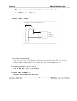
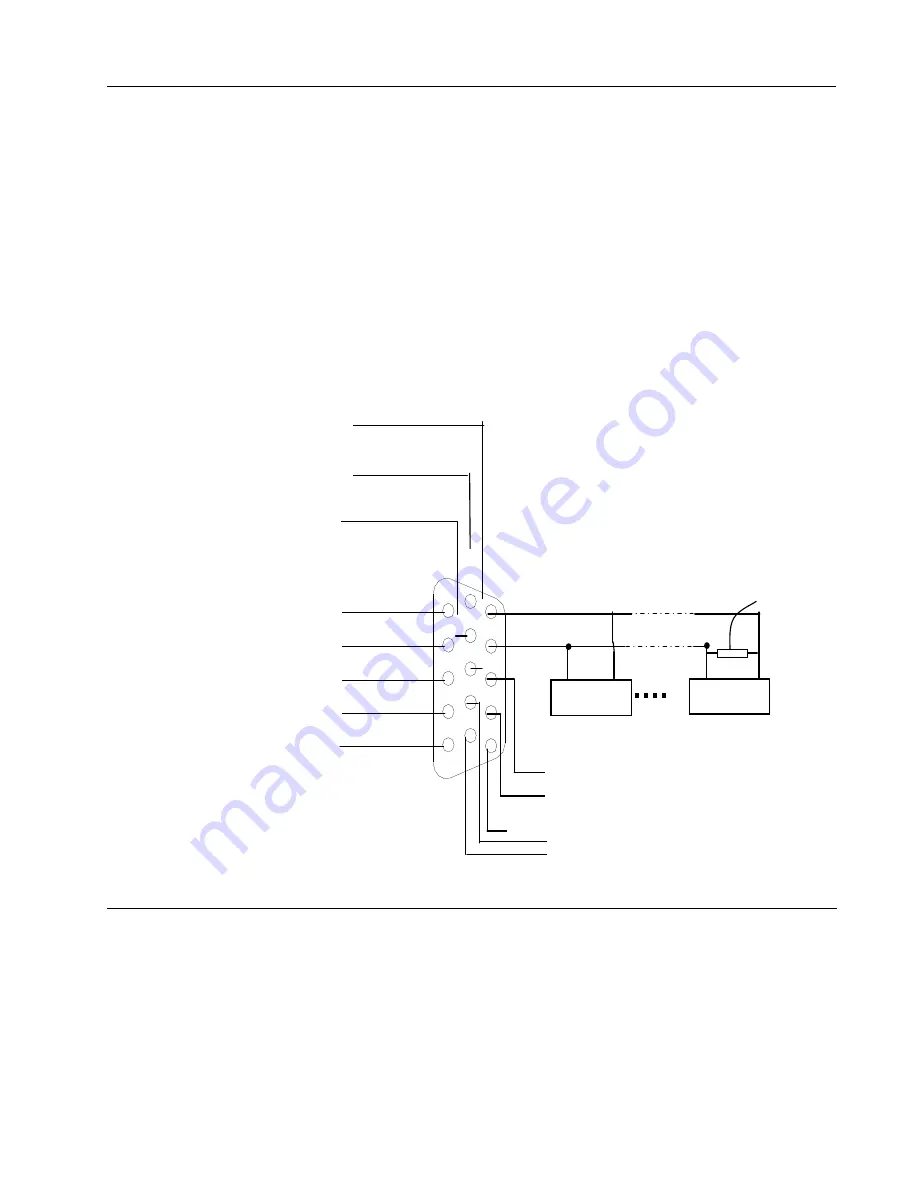
If you want to control Camera pan-tilt-zoom (P/T/Z) or activate the DVR Output relay, the 25-pin RS485
connection must be used. See detail below.
The RS485 port connection can control various (P/T/Z) Cameras, and the specific model or protocol can be
selected from the Control Menu in System settings.
The DB25 pin outs are marked below. The definition of the pin outs are as follows: The broken line in the
graph indicates inside connection that have already been wired.
!
w"
t
E
E
E
s$#%%#}##|;'&(&#q)+*-,t./&(&(q)*-,s
á
0
"
E
21
&(&(q)345t6,(7#wv98vx#|};:
<= =
&(&(q)345,#7(w%v>3#}%?:
<
txr
&(&(q)345
,(7#w%v>3}%
ALARM INPUT ALARMIN4
@
@
@
ALARM INPUT ALARMIN1
+12V output
GROUND LINE
120
A/BDCDEGFHEJIHKJLDMJC
RS485 A Line
RS485 B Line
Decoder
Decoder
B A
B A
Alarm output 2 common terminal ALARMOUT3_C
Alarm output2 common open contact ALARMOUT3_NO
ALARMOUT 1 NORMAL CLOSE CONTACT
ALARMOUT 1_ COMMON TERMINAL
A LARMOUT 1 NORMAL OPEN CONTACT
1
2
4
3
5
6
7
8
9
10
11
12
13
14
15
Alarm output3 common terminal ALARMOUT3_C
Alarm output3common open contact ALARMOUT3_NO

