4
CHAPTER1
HARDWARE AND OPERATION MODE INSTRUCTION
1.1
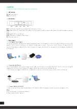
LED indicator
Green:
Power Indicator
Blue:
WiFi Indicator
1.2
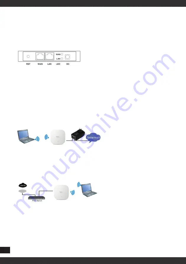
AP Interface
RST:
Reset Button, it make AP revert to default data after press it 15 sec.
WAN:
Gigabit WAN Port, connect with ADSL modem or Internet mainly. It will be LAN port under Wireless AP and WiFi Repeater operation
mode
LAN:
Gigabit LAN Port to end users
LED:
LED Indicator of WAN port and LAN port
DC:
DC power connector
1.3
Power Supply
1.3.1
PoE Adapter Power Supply
The connection diagram showed as next image, internet cable connect to PoE adapter’s LAN Port, Ceiling AP’s WAN port connect to PoE
adapter’s PoE Port, then PC will access into ceiling AP through cable or wireless. Please note, if the PD Wireless AP support 48V PoE,
then the PoE adapter should be 48V PoE. If the PD wireless AP support 48V IEEE 802.3af standard PoE, the PoE adapter should be 48V
PoE standard.
1.3.2
Powered by PoE Switch
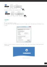
The connection diagram shows as next image, Internet cable from PoE Switch to Ceiling AP’s WAN Port, then PC access into ceiling AP
wired/wireless. Pls note, if the PD Wireless AP support 48V PoE, then the PoE switch should be 48V PoE,.
If the PD wireless AP support 48V IEEE 802.3af standard PoE, m the PoE switch should comply with 802.3af 48V PoE standard.
1.3.3
Connect Wireless AP with PC
Use can connect the PC with wireless AP by Wireless SSID and LAN cable: The diagram of wireless connection showed as follow:
Note:
SSID è MachPower2.4 / MachPower5.8 (default)
SSID password è 12345678 (default)


