background image

Page 28 


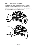
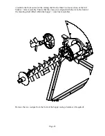
Section 5 – Machine operation / speed setting 

 
The continuous mixer will discharge approx 132 LBS (78 LBS) of course grain sand 
@280 RPM Max RPM, with the knob at half scale the RPM will be 140 and the delivery 
approx 66 LBS (39 LBS). 
 
The following are to be completed by trained and experienced persons, familiar with the 
mixing system provided. 

 
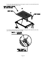
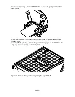
1.  Fill the D-25 hopper with material. By dropping bags over the bag breaker, 

twisting left and right by approx 15 degrees, then lifting both ends of the bag to 
tear it in the middle. Allow the material to drop into the hopper, then remove the 
bag from the grid area into a disposal container. 

2.  Turn the water supply OFF and establish the speed the mixer should run, by either 

measuring the output within a certain time, or by weighing the output within a 
certain time. 

3.  Turn ON the water supply, and disconnect the hose to the mixing nozzle. Place 

the hose end on the ground where water will not damage anything. 

4.  Hang a bucket on the end of the mixing nozzle to catch material. 
5.  Turn the machine ON in the FWD direction and observe water to flow through the 

meter. Quickly set the water flow to suit the amount of material being delivered 
(base mix ration on manufacturers information). STOP the machine. 

6.  Remove the bucket and return the contents to the hopper. Reconnect the hose to 

the mixing nozzle. 

7.  The machine is now ready for use. 

General notes for operation 

 
Turn main power switch on.  
Push start button.  
Adjust speed to desired output.  
Do not let hopper run below the top of the mixing shaft while mixing or the mix rations 
will change.  
To stop machine push the stop button.  
When cleaning the mixer, do not remove grate while mixer is running.  
Do not spray water on or in control box. Control box should be wiped down with a damp 
rag. 
If access is required in to the hopper, disconnect power source before removing grate. 
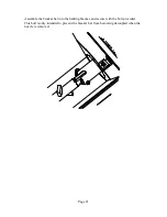
Mixer can be disassembled by removing wedges, this facilitates easier transport and final 
clean up.  
Always check hoses and cords for wear.  
The unit runs on high voltage and is capable of high torques. 
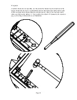
Ensure that, after every 3 hours of operation, that the nozzle is removed together with the 
mixing shaft for cleaning. Check that the feed screw section of the shaft (in the hopper) is 
cleaned at the end sticking from the hopper as this is prone to water contamination, and 
can suffer a material build up. 


Summary of Contents for 60010054

Page 1: ...0085 ASSY MIXER CONTINUOUS D25 78LB 60010093 ASSY MIXER CONTINUOUS D25 2 60010084 ASSY MIXER CONTINUOUS D25 132LB 3 PHASE 60010108 ASSY MIXER CONTINUOUS D25 78LB 3 PHASE 60010098 ASSY MIXER CONTINUOUS...

Page 2: ...efore starting this machine please complete the following Machine Date of purchase Machine serial number Please read the following information contained within this manual and fully familiarize yourse...

Page 3: ...screw 60010074 ASSY HELIX CONT MIXER 78LB 11 Dosing Feed screw 60010088 ASSY HELIX CONT MIXER 2 11 Wear liner assembly Seal Seal clamp Bolts and Washers 12 Electronic Drive module 13 Drive motor unit...

Page 4: ...empting to operate the machine Ensure that all fasteners are present and correctly fitted before attempting to start or operate the machine Ensure that the nozzle unit is correctly fastened to the fro...

Page 5: ...e 60 50Hz via an electronic variable speed inverter supplied by two phase 208VAC 60 Hz or 220 240 VAC 50 60Hz or 440 480 VAC 60Hz 3phase Input power The inverter control box allows the user to adjust...

Page 6: ...Machine illustrations Machine 1 Hopper unit 2 Mixing nozzle assembly 3 Base frame assembly 4 Inverter drive module 5 Drive motor 6 Water control module 7 Bag Breaker 8 Water hose assy 9 Power cord and...

Page 7: ...te end of the unit with the handle thus also being mirrored The control panel assembly on handle assembly can be moved by pulling the pins keeping the handle assembly in place in the frame then slidin...

Page 8: ...Page 8 Hopper unit...

Page 9: ...Page 9 Mixing Nozzle Assembly 132LB shown 60010056 The complete mixing nozzle assembly is available in three different versions low output 78LB standard output 132LB and High output 2...

Page 10: ...er Dosing Mix D25 132LB shown 60010066 Alternatively the complete Assy Breaker dosing mix is available in three different versions Low output 78LB 6001007 Standard output 132LB 60010066 shown and High...

Page 11: ...combinations of low standard and high output shaft tube etc assemblies is the dosing feed screw Dosing Feed screw 60010069 ASSY HELIX CONT MIXER 132LB Dosing Feed screw 60010074 ASSY HELIX CONT MIXER...

Page 12: ...Page 12 Wear liner assembly Seal Seal clamp Bolts and Washers...

Page 13: ...t fits into the 3 Phase outlet of the module The module has a main power isolator a combine stop start switch a spring return reverse switch a speed control potentiometer internal breakers for each in...

Page 14: ...x remove the two pins from either side of the frame assembly and withdraw the handle with the control box mounted to it from the main frame Do not fully withdraw the handle and box as damage could res...

Page 15: ...Page 15 Drive motor unit The machine is supplied with an electric motor drive...

Page 16: ...e flow rate can be adjusted at the base of the flow meter using the control knob When the unit is left standing for any length of time or to be stored for freezing temperatures the water within the sy...

Page 17: ...cking the wheels in the down position then using the nozzle like the handles on a wheel barrow Lift the machine at the wheel end and lift UP the axle lock bar and the wheels will drop to the ground At...

Page 18: ...Page 18 Once in position the lock bar can be raised and the whole unit will drop lifting the axle and the wheels The lock bar on level ground will catch the axle to keep it from lowering...

Page 19: ...of your machine and the items checked prior to shipment Keep this document for your records Remove the unit from the packing and the pallet If required Pre assemble the motor assembly onto the rear o...

Page 20: ...he top of the hopper to allow you to rotate the breaker bar assembly already fitted inside the unit If required rotate the breaker bar in the hopper to engage the flat end into the slot in the drive h...

Page 21: ...Page 21 Assemble the breaker bar into the hauling bracket and secure with the bolt provided This bolt is only intended to prevent the breaker bar from becoming decoupled when the nozzle is removed...

Page 22: ...er Rotate the feed screw round until the hole in the breaker bar and the holes in the feed screw align Once aligned then the roll pin must be driven into the holes until it sticks out either end by ap...

Page 23: ...ted two rear sections of the full breaker mixer assembly Ensure that the cross pin is aligned with the slot in the front of the metering shaft fitted within the hopper wear liner assembly Remove the t...

Page 24: ...e seal and assemble the nozzle Assemble the nozzle over the end of the mixer shaft along its length then over the wear liner assembly ensure that the end of the mixing shaft locates into the bearing i...

Page 25: ...assemble the safety grid to the top of the hopper using the grid keepers and bolts originally fitted Ensure that the bag breaker is fitted to the grid and is facing upwards CAUTION as the sharp edge...

Page 26: ...be 220VAC and capable of supplying 30A on each leg phase Turn the breakers OFF in the box and remove it from the bus bar to ensure that no voltage exists on the cables 5 Make the connection between th...

Page 27: ...tube for maximum shear effect 10 Turn the direction switch from FWD to REV observe the machine to turn the shaft and in turn the mixing shaft in reverse 11 Press the stop button 12 Connect a water sup...

Page 28: ...to flow through the meter Quickly set the water flow to suit the amount of material being delivered base mix ration on manufacturers information STOP the machine 6 Remove the bucket and return the con...

Page 29: ...e material build up After each clean down grease the external square bore mixing nozzle bearing until grease can be seen oozing from the bearing seals Do not grease any of the mixing shaft connections...

Page 30: ...nsportation charges unless specifically identified and authorized in writing by Machine Technologies Nor does the warranty apply to any unit upon which repairs or unauthorized alterations have been ma...

Reviews: