4 Dism antling/Assem bly
4.12 R em ote controlled brake (pneum atic)
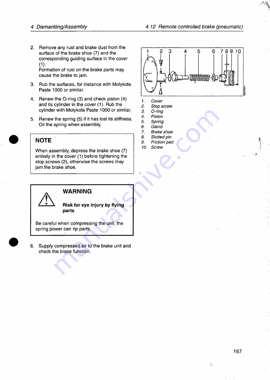
2. Remove any rust and brake dust from the
surface of the brake shoe (7) and the
corresponding guiding surface in the cover
0)-
Formation of rust on the brake parts may
cause the brake to jam.
3. Rub the surfaces, for instance with Molykote
Paste 1000 or similar.
4. Renew the O-ring (3) and check piston (4)
and its cylinder in the cover (1). Rub the
cylinder with Molykote Paste 1000 or similar.
5. Renew the spring (5) if it has lost its stiffness.
Oil the spring when assembly.
NOTE
When assembly, depress the brake shoe (7)
entirely in the cover (1) before tightening the
stop screws (2), otherwise the screws may
jam the brake shoe.
2 3
•\\
i
6 7 8 9 10
“L
.
D ^ O P iii
1. Cover
2. Stop screw
3. O-ring
4. Piston
5. Spring
6. Giand
7. Brake shoe
8. Slotted pin
9. Friction pad
10. Screw
I
A
WARNING
Risk for eye injury by flying
parts
Be careful when compressing the unit, the
spring power can rip parts.
6. Supply compressed air to the brake unit and
check the brake function.
167
Summary of Contents for Tetra Centri A 614HGV-14C
Page 6: ......
Page 34: ...2 10 Tightening of screws 2 General advice j 34...
Page 40: ...3 3 Vibration report separator 3 Directions for maintenance 40...
Page 45: ...4 Dismantling Assembly 4 4 Outlet single ph 4 2 Inlet 45...
Page 51: ...4 Dismantling Assembly 4 4 Outlet singlephase separators 4 3 3 A B F B F 51...
Page 63: ...4 Dismantling Assembly 4 4 Outlet single phase separators 4 4 2 BM BB 818 D 718 high flow 63...
Page 73: ...4 Dismantling Assembly 4 4 Outlet single phase separato 4 5 Machine top part 73...
Page 74: ...4 5 Machine top part 4 Dismantling Assembly...
Page 131: ...4 Dismantling Assembly 4 9 Frame parts 4 9 Frame parts 131...
Page 134: ...SW i f 4 10 Vertical driving device C t O 134 4 Dismantling Assembly...
Page 140: ...4 10 Vertical driving device 4 Dismantling Assembly 140 v V Vp r 5 Cr i...
Page 146: ...4 10 Vertical driving device 4 Dismantling Assembly H r 146...
Page 178: ...4 17 Mounting on the foundation feet 4 Dismantiing Assembiy I 178...
Page 185: ...5 Lubrication 5 2 Lubricants 185 I...
Page 196: ...D 714HGV 34C...
Page 213: ...2 Machine bottom part 10 6 7 8 9 B A 25 23 V...
Page 215: ...2 1 Driving device horizontai 2 Machine bottom part 25...
Page 217: ...2 2 Driving device verticai 2 Machine bottom part 29 28 27 c 5 16 1 1 27...
Page 219: ...2 3 Worm wheel guard 2 Machine bottom part f 2 3 29...
Page 221: ...2 4 Remote control brake 2 Machine bottom part 31...
Page 223: ...2 5 Inlet device SMS coupling 2 Machine bottom part 12 13 19 20 33...
Page 225: ...2 5 Inlet device SMS coupling 2 Machine bottom part 12 13 19 20 33...
Page 227: ...2 6 Inlet device Clamp coupling 2 Machine bottom part 12 13 21 35...
Page 229: ...3 Machine top part 37...
Page 231: ...3 1 Paring disc device 3 Machine top part i 39...
Page 233: ...4 Cyclone 41...
Page 235: ...5 Outlet pipe SMS Connection 5V 43...
Page 237: ...6 Outlet pipe Clamp Connection 45...
Page 239: ...7 Separator bowl Clarifier 23 1 47...
Page 241: ...8 Outlet device SMS coupling 49...
Page 243: ...9 Parts for mounting of CT motor A 51...
Page 245: ...10 Parts for mounting of standard motor VFD 17 17A 53...
Page 247: ...11 Operating water module compact 55...
Page 249: ...12 Fittings for OWMC 57...
Page 251: ...13 Set of plates 59...
Page 253: ...14 Speed sensor kit Sensor included 61...
Page 255: ...15 Vibration sensor kit Sehenek ci 63...
Page 257: ...16 Vibration sensor kit Monitran A 65...
Page 259: ...17 Lock switch kit 67...
Page 263: ...18 Set of tools 71...
Page 265: ...18 Set of tools 75 76 77 M Mh 78 81 79 82 80 83 84 85 d 86 73...
Page 267: ...19 Intermediate service kit SMS coupling 75...
Page 269: ...20 Major service kit 77...
Page 271: ...21 Service kit for foundation feet 79...
Page 273: ...22 OWMC service kit 81...
Page 274: ...D 714HGV 34C 82...


