background image

7

OPERATION MANUAL

UNPACKING

This machine was carefully packaged for safe transport. When unpacking, separate all enclosed

items from packaging materials and inspect them for shipping damage. If items are damaged,

please contact your distributor.

NOTE: Save all the packaging materials until you are completely satisfied with the machine and

have resolved any issues with the distributor, or the shipping agent.

When unpacking, check the packing list to make sure that all parts shown are included. If any 

parts are missing or broken, please contact the your distributor.

4 SETUP

The unpainted surfaces of the machine have been coated with a waxy oil to protect them from 

corrosion during shipment. Remove the protective coating with a solvent cleaner or a citrus 

based degreaser.

Optimum performance from your machine will be achieved when you clean all moving parts or 

sliding contact surfaces that are coated with rust prevented products.

It is advised to avoid chlorine based solvents, such as acetone or brake parts cleaner, as they 

will damage painted surfaces and strip metal should they come in contact. Always follow the 

manufacturer’s instructions when using any type of cleaning product.

CLEAN - UP

SITE PREPARATION

When selecting the site for the machine, consider the largest size of workpiece that will be 

processed through the machine and provide enough space around the machine for operat-

ing the machine safely. Consideration should be given to the installation of auxiliary equip-

ment. Leave enough space around the machine to open or remove doors/covers as required 

for the maintenance and service as described in this manual.

It is recommended that the machine is anchored to the floor to prevent tipping or shifting.  It 

also reduces vibration that may occur during operation. 

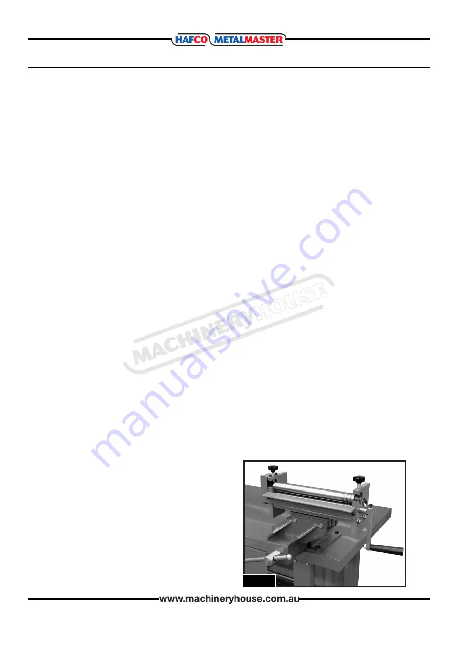
MOUNTING IN VISE

There are substantial forces exerted on the metal 

curving rolls during operation. With this in mind, 

the curving roll must be firmly secured in a vise 

that is solidly attached to a workbench that will 

support the weight and dynamic forces of the 

operation. (Fig. 2)

F

ig

. 2

Summary of Contents for Hafco Metalmaster S267

Page 1: ...OPERATION MANUAL Edition No SRG 12 1 Date of Issue 05 2021 Model SRG 12 Order Code S267 Manual Sheet Metal Curving Rolls...

Page 2: ...olls MACHINE SRG 12 MODEL NO SERIAL NO DATE OF MANF Distributed by www machineryhouse co nz MACHINE DETAILS NOTE This manual is only for your reference Owing to the continuous improvement of the Hafco...

Page 3: ...Groove Positions No 3 Dimensions L x W x H cm 75 x 19 5 x 39 3 Shipping Dimensions L x W x H cm 42 5 x 18 x 20 5 Nett Weight kg 13 6 IDENTIFICATION A Thickness Adjustment Knobs F Vise Lug B Upper Roll...

Page 4: ...nd ear protection Always wear ANSI approved impact safety goggles Wear a full face shield if you are producing metal filings or wood chips Wear an ANSI approved dust mask or respirator when working ar...

Page 5: ...lude but are not limited to Being struck by ejected parts of the machinery Being struck by material ejected from the machinery Contact or entanglement with the machinery Contact or entanglement with a...

Page 6: ...ure no slip trip hazards are present Be aware of other people in the area and ensure the area is clear before using equipment OPERATIONAL SAFETY CHECKS Adjust both ends of the rollers evenly Take care...

Page 7: ...It is advised to avoid chlorine based solvents such as acetone or brake parts cleaner as they will damage painted surfaces and strip metal should they come in contact Always follow the manufacturer s...

Page 8: ...es or seek training from an experienced operator before performing any unfamiliar operations Above all your safety should come first Thickness Adjustment Knob Raises and lowers the upper roller to adj...

Page 9: ...Have your machines model number serial number date of manufacture on hand these can be found on the specification plate mounted on the machine 2 A scanned copy of your parts list diagram with required...

Page 10: ...10 OPERATION MANUAL SPARE PARTS DIAGRAM...

Page 11: ...5 IDLE SHAFT WASHER 8MM RIGHT STAND BUSHING WASHER 6MM SPRING WASHER 6MM SCREW M6X12 2 1 1 2 1 2 4 1 4 1 3 3 8 9 15 16 17 18 19 20 21 22 23 24 25 26 27 28 SPRING WASHER 8MM GEAR UPPER SHAFT LOWER SHAF...

Page 12: ...the off position before re connecting 14 Use correct amperage extension cords Undersized extension cords overheat and lose power Replace extension cords if they become damaged 15 Keep machine well ma...

Page 13: ...erstand the machines controls Make sure you understand the use and operation of all controls 8 Work area hazards Keep the area around the Rolling machine clean from oil tools chips Pay attention to ot...

Page 14: ...CONTROL Safety officer PLANT SAFETY PROGRAM No Hazard Identification Item Hazard Assessment CRUSHING CUTTING STABBING PUNCTURING MEDIUM Wear gloves to prevent cuts from sharp material B C LOW Risk Co...

Reviews: