background image


The Apollo I Breakout Board provides a flexible, plug-in-play interface for the Mach3 CNC software using standard

computer parallel ports.  Its key features include the following:

6 Axis Control

Spindle Control (Clockwise, Counterclockwise, and 0-10VDC Analog)

9 Inputs & 8 Outputs

Emergency Stop Circuit

Hardware and Drive Enable Circuit

1.1 Overview

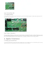
Use the diagram below as a reference throughout the manual.


Figure 1 Apollo I Overview

The purpose of this manual is to give you all the information you need to use the Apollo I Breakout Board. Written in

simple step by step instructions, this manual can be used by anyone who has a basic understanding of your machine

and basic computer skills.


Apollo I User Manual - Mach3

1. Introduction

WARNING

Do NOT connect 115VAC to any part of the Apollo I Breakout Board. It could cause serious damage to your

board. 

Summary of Contents for Apollo I

Page 1: ...Circuit 1 1 Overview Use the diagram below as a reference throughout the manual Figure 1 Apollo I Overview The purpose of this manual is to give you all the information you need to use the Apollo I Br...

Page 2: ...s and Terminal Blocks Max Pulse Speed 45 kHz Spindle 1 Relay Outputs Clockwise CW and Counterclockwise CCW Analog Signal 0 10VDC Outputs 8 Voltage 7V 48VDC Max Current 250mA Commons 2 Inputs 9 Sinking...

Page 3: ...ort out Place the Apollo I as close to the control as possible If the parallel port cables are longer than 12 then you may have issues with electrical noise 2 2 Supply Power To turn on the Apollo I yo...

Page 4: ...nable circuit and should only be used for testing purposes When the CP jumper is connected to the bottom two pins the green and blue enable LEDs should turn on See Hardware Enable and Drive Enable Sec...

Page 5: ...Near the top select the Device Manager For Windows XP click on theHardware tab first 3 Expand the Ports COM LPT to see all the parallel ports on your control For all MachMotion controls PCI ECP Parall...

Page 6: ...Press Apply and then OK If you used a default XML from MachMotion s website your parallel ports should now be set up Press the Reset button in Mach3 if it is flashing The enable LED shown in Figure 14...

Page 7: ...nable Figure 10 Emergency Stop Connection Note Nothing will work on the Apollo I Breakout Board unless the Emergency Stop terminals are connected together Emergency stop input is set up inside Mach3 b...

Page 8: ...able The 5V and 24V enable signals can be used for any low current applications The hardware enable relay can be used for higher current applications if you supply the voltage source The signals are l...

Page 9: ...the Drive Enable 4 2 Drive Enable Drive enable is used to enable all your drives When activated the drive enable relay connects the external enable EXT to the servo enable SOV terminals on TB2 The sig...

Page 10: ...axis control cables just connect your signal directly to SOV Drive enable uses the same output as the hardware enable SeeFigure 15 for the Charge Pump setup Now all the LEDs on the Apollo I besides th...

Page 11: ...able 2 Axis Control Mod Jack Pinouts For any drive from MachMotion you can plug it directly into the axis control mod jacks Note For more information on the Drive Enable signal seeDrive Enable section...

Page 12: ...ready The port and pin numbers must be set up as shown below for anything to work Figure 21 X Y and Z Axes Enabled 1 Press Apply and then OK Your axes should now be enabled Note The Dir LowActive and...

Page 13: ...tance of one motor turn This gives you what Mach3 calls your Steps per Steps per Encoder Counts Distance of One Motor Turn 1 Finally you can calculate your velocity by multiplying your motor s RPM by...

Page 14: ...nter your velocity as shown below Figure 24 Velocity in Motor Tuning Press SAVE AXIS SETTINGS before clicking on another axis or closing out theMotor Tuning and Setup window 5 3 2 Calibration Wizard T...

Page 15: ...axis or closing out theMotor Tuning and Setup window 5 4 Calculating Backlash The Apollo I has backlash compensation Use the MDI line to enter g code to move your axes To calculate your machine s bac...

Page 16: ...eneral Config The value Shuttle Accel in seconds is how fast your backlash will be applied Figure 28 Shuttle Accel Below is a table of common values Drive Type Seconds Steppers 1 to 0 1 Servos 0 01 to...

Page 17: ...l now move the opposite direction than it did before 5 6 Slaving an Axis To configure an axis as a slave follow the steps outlined below 1 Click Config Slave Axis on the main menu bar It will display...

Page 18: ...If these LEDs turn on correctly then your spindle is set up Figure 33 Spindle LEDs 6 1 Wiring up Your Spindle 6 1 1 Spindle Control Your spindle can be connected into RJ1 or directly into the termina...

Page 19: ...spindle into the terminals on TB2 as shown below Figure 35 Spindle Control Terminals The terminals and the RJ45 connector both use the same signals Use whatever method is easiest 6 2 Setting up the S...

Page 20: ...spectively Set the Active Low column to a red X See the figure below Figure 37 Spindle Outputs 1 Finally click on the Spindle Setup tab Make sure the check boxDisable Spindle Relays is unchecked and t...

Page 21: ...r example one pulley could be set to 75 to 300 RPM for a low speed at 300 RPM the control will output 10V A medium speed pulley could go from 300 to 1200 RPM and high speed pulley could run from 1200...

Page 22: ...4 Turning on Your Spindle To turn on your spindle begin by setting a spindle speed Navigate toProg Run and click on the SpindleS user input Enter your speed and press Send as shown in Figure 41 Figur...

Page 23: ...n M3 Clockwise M4 Counter Clockwise M5 Stop Table 7 Spindle M Codes 6 5 Reversing Direction To reverse a pulley s direction go toConfig Spindle Pulleys Select the pulley that you want to reverse and t...

Page 24: ...the jumpers near the bottom right of Apollo I The jumpers start counting from the left at X0 and increment up to X15 X9 X15 are not used for the Apollo I Each jumper corresponds to an input For examp...

Page 25: ...put you must supply 24V to the input A floating signal or a ground will not turn on the input The LED corresponding to the input will turn on brightly when the input is activated For a more detailed d...

Page 26: ...rcing Inputs PNP For 2 5 10V inputs connect your positive voltage to the C0 terminal and your ground to C0 Completely remove the jumper corresponding to the input and connect XNL where N represents th...

Page 27: ...p then you may have to completely remove the jumper You will have to use a 3 9k ohm resistor and connect it between XSL and C0 where S is your input number For example if you are using input X5 connec...

Page 28: ...the procedure below 1 On the menu bar click onConfig then Ports and Pins 2 Select the Input Signals tab Scroll down to the desired input There are 4 inputs and 15 OEM triggers An OEM trigger acts exac...

Page 29: ...ins and inside the MachMotion plugin Read Advanced Options section for more information on how to use inputs inside the plugin The Apollo I has 8 logic outputs that can be used for any low current app...

Page 30: ...s you can provide your own voltages for the commons In the example below two separate power supplies are used Notice that since the power is supplied externally each output can draw up to 250mA Figure...

Page 31: ...heck box Then your output will only turn off when you activate your output 2 Press Apply and then OK to save your settings Now your output should be set up 8 3 Using Your Outputs There are a few ways...

Page 32: ...PlugIn Control MachMotion Config to open the MachMotion plugin Figure 63 MachMotion Plugin IO Configuration In general only change values and settings in the red boxes shown above The rest of the opti...

Page 33: ...Cycle Start Now whenever Input4 is active E Stop will be flagged Figure 66 MachMotion Plugin User Defined Messages The User Messages can be configured to have custom messages displayed Each input will...

Page 34: ...is available at our website https machmotion com warranty The MachMotion Team http www machmotion com 14518 County Road 7240 Newburg MO 65550 573 368 7399 Fax 573 341 2672 Revision 6 Created Thu Jul 5...

Reviews: