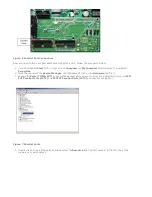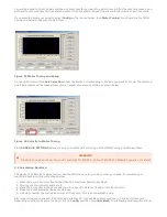
1. On the menu bar, click Config and then Ports and Pins. A window called Engine Configuration… Ports and
Pins will pop up. Select the Motor Outputs tab and you will see the axis setup as pictured below.
Figure 20 Axis Setup
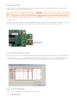
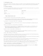
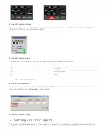
1. Click on the red “X” to enable an axis. If there is a green check mark next to the axis, then the axis is enabled
already. The port and pin numbers must be set up as shown below for anything to work.
Figure 21 X, Y, and Z Axes Enabled
1. Press Apply and then OK. Your axes should now be enabled.
Note: The Dir LowActive and Step Low Ac… columns are not used for the Apollo I Breakout Board.
Now you should be able to jog your axes!
WARNING
Your machine has not be calibrated so it could jog at extremely high speeds and move erroneous distances.
Also, no limits have been set up so you could cause DEATH, INJURY or serious PROPERTY DAMAGE if you are not
careful.


