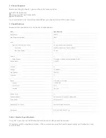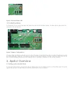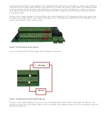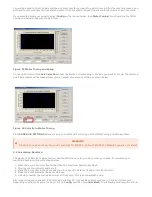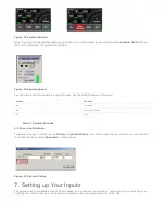
Figure 14 Hardware Enable LEDs
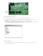
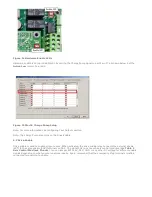
Hardware enable is set up inside Mach3 by setting the Charge Pump signal to port 2 pin 17 as shown below. Set the
Active Low column to a red X.
Figure 15 Mach3 Charge Pump Setup
Note: For more information see Configuring Your Outputs section.
Note: The Charge Pump also turns on the Drive Enable.
4.2 Drive Enable
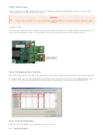
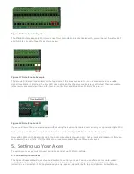
Drive enable is used to enable all your drives. When activated, the drive enable relay connects the external enable
(EXT) to the servo enable (SOV) terminals on TB2. The signal SOV runs to each axis control mod jack (See Table 2
Axis Control Mod Jack Pinouts). You can jumper EXT to 5V, 24V, GND, or any other DC voltage for different enable
signals depending on what your servo drives require. Again, remember that the emergency stop terminals must be
connected for anything to enable.


