REPAIR INSTRUCTIONS, PART 1
Page 189
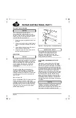
SALVAGING A DAMAGED VALVE LIFTER
BORE
Occasionally, a failure will result in severe wear
and breakage of the roller and roller axle. These
parts will then separate from the lifter body.
Subsequently, the lifter legs (which had retained
the axle in the lifter body) become bent-outward
and are driven up into the lifter bore by the cam
lobe. This action damages the bottom 1/4 to
3/8 inch (6.35 to 9.52 mm) of the bore and will
prevent installation of the new lifter. It is
necessary to clean up the damaged bore area
with a file, stone or emery paper using care to
remove
all
high spots from the bore. The goal is
to clean up the areas of raised metal, but not to
enlarge the bore diameter. Any remaining nicks
or scores (low spots) do not inhibit proper
function of the parts and will cause no problem.
After removing any raised metal, use a flex-hone
to lightly hone the bore.
Another condition sometimes encountered is a
small amount of scuffing or foreign particle
scoring in a lifter bore. This condition can inhibit
static-free movement of a lifter. This will not
cause a lifter hang-up in engine operation, but is
sometimes noticed during lifter removal or
installation. If this condition is encountered, use a
flex-hone to lightly hone the bottom area of the
lifter bore, trial-fitting the lifter until the high spots
have been removed and free movement is
re-established.
Whenever a lifter bore is reworked or honed, be
sure that all the metal and honing debris is
cleaned from all affected areas by flushing with a
fresh supply of suitable brake/parts cleaner.
LIFTER BORE CLEANING AND LIFTER
CHECKS
While the camshaft is removed and lifter bores
are relatively accessible, it is a good practice to
clean all the lifter bores and then trial-fit all the
lifters into their respective bores and H-rings.
Clean and trial-fit lifters as follows:
1. Clean all lifter bores with a fresh supply of
suitable brake/parts cleaner. Ensure all
Loctite
®
residue and dried contamination
has been removed from the lifter bore and
H-ring area.
2. Trial-fit a lifter back into its original lifter bore
by aligning the lifter flats with the H-ring flats.
Use only light finger pressure when installing
the lifters. Verify that the lifter has complete
freedom of movement in the bore and H-ring
in both the upward and downward
directions. When the lifter is seated, it should
be possible to rotate it slightly from left to
right. If the lifter is sticky or tight, or if
additional force was required to install the
lifter, proceed as follows:
a.
Try the lifter in another lifter bore. A
stack-up of component tolerances can
result in a lifter being free in another
bore. This is acceptable.
b.
If the problem persists when the lifter is
tried in another bore, replace the lifter.
c.
If the problem is confined to a particular
bore, determine if the lifter tightness is
due to the lifter or the H-ring. If the bore
is the problem, perform a bore clean up
and hone as described in “SALVAGING
A DAMAGED VALVE LIFTER BORE”
on page 189. If the lifter is tight in the
H-ring, replace the lifter or H-ring as
determined by a trial-fit of another lifter.
3. Once all lifters have been trial-fit to their
respective bores and H-rings, label each
valve lifter and place on a clean work
surface until reassembly.
5-111.bk Page 189 Monday, July 10, 2006 2:26 PM
Summary of Contents for ASET AC
Page 6: ...TABLE OF CONTENTS Page iii TABLE OF CONTENTS 5 111 bk Page iii Monday July 10 2006 2 26 PM...
Page 14: ...INTRODUCTION Page 1 INTRODUCTION 5 111 bk Page 1 Monday July 10 2006 2 26 PM...
Page 23: ...Page 10 NOTES 5 111 bk Page 10 Monday July 10 2006 2 26 PM...
Page 96: ...COMPONENT LOCATOR Page 83 COMPONENT LOCATOR 5 111 bk Page 83 Monday July 10 2006 2 26 PM...
Page 99: ...Page 86 NOTES 5 111 bk Page 86 Monday July 10 2006 2 26 PM...
Page 100: ...TROUBLESHOOTING Page 87 TROUBLESHOOTING 5 111 bk Page 87 Monday July 10 2006 2 26 PM...
Page 140: ...MAINTENANCE Page 127 MAINTENANCE 5 111 bk Page 127 Monday July 10 2006 2 26 PM...
Page 153: ...Page 140 NOTES 5 111 bk Page 140 Monday July 10 2006 2 26 PM...
Page 383: ...Page 370 NOTES 5 111 bk Page 370 Monday July 10 2006 2 26 PM...
Page 479: ...Page 466 NOTES 5 111 bk Page 466 Monday July 10 2006 2 26 PM...
Page 480: ...SPECIFICATIONS Page 467 SPECIFICATIONS 5 111 bk Page 467 Monday July 10 2006 2 26 PM...
Page 505: ...Page 492 NOTES 5 111 bk Page 492 Monday July 10 2006 2 26 PM...
Page 513: ...Page 500 NOTES 5 111 bk Page 500 Monday July 10 2006 2 26 PM...
Page 519: ...Page 506 NOTES 5 111 bk Page 506 Monday July 10 2006 2 26 PM...
Page 520: ...APPENDIX Page 507 APPENDIX 5 111 bk Page 507 Monday July 10 2006 2 26 PM...
Page 528: ...INDEX Page 515 INDEX Index fm Page 515 Monday July 10 2006 2 48 PM...
Page 535: ...Page 522 NOTES Index fm Page 522 Monday July 10 2006 2 48 PM...

