REPAIR INSTRUCTIONS, PART 1
Page 217
224
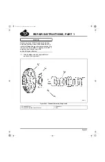
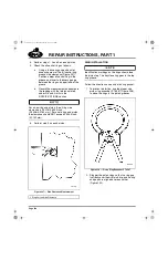
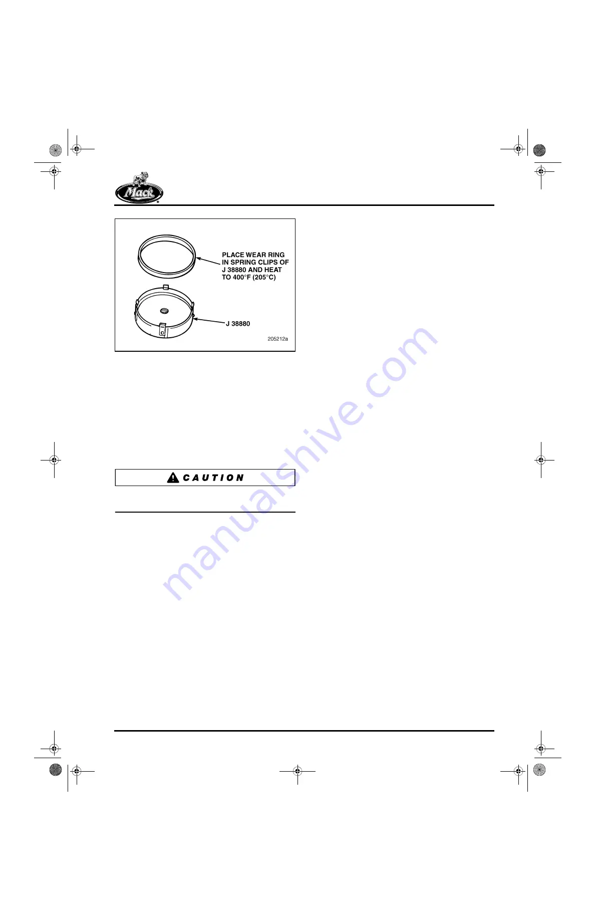
Figure 224 — Crankshaft Wear Ring Installation
2. Heat the wear ring and wear ring installer
together in a temperature-controlled oven or
on a hot plate, with the wear ring on the
bottom and installed in the spring clips of the
installer. Work as close as possible to the
engine to avoid heat loss after heating the
ring. Heat to 400
°
F (205
°
C). Do not install
the driver handle at this time. This allows the
wear ring to maintain sufficient heat until it is
fully installed on the flange.
Do not heat the wear ring with a torch. This type
of heat source will not heat the ring evenly.
3. Thoroughly clean and dry the crankshaft oil
seal mounting flange.
4. After the wear ring is sufficiently heated, use
heat-resistant gloves to install the universal
driver handle J 8092 into the threaded hole
at the center of the installation tool.
5. Remove the wear ring and installation tool
from the oven or hot plate and immediately
place it in position on the crankshaft flange.
Push the wear ring onto the flange until the
installation tool is fully seated against the
end of the flange. As the wear ring cools, it
will shrink-fit onto the crankshaft flange.
6. Allow the wear ring to cool completely. Then
remove the installation tool.
WEAR RING WITH DOUBLE-LIP TEFLON
®
SEAL (AUTOMATIC TRANSMISSION)
The oversize inside diameter lip seal and wear
ring are shipped as an assembly with the seal
installed on the wear ring. For this combination,
the seal and the wear ring are installed as an
assembly. Refer to the crankshaft rear oil seal
installation procedures under Engine
Reassembly in the REPAIR INSTRUCTIONS
section.
Flywheel Inspection and
Resurfacing
[212 UB]
The flywheel is a design with an integral,
non-replaceable ring gear. If the ring gear teeth
are in good condition, the flywheel surface should
be checked as follows:
1. Inspect the flywheel to determine if it
requires resurfacing. The wear areas should
be measured using a straightedge across
the friction face and a thickness gauge. If the
wear measurement is 0.020 inch
(0.508 mm) or less, the flywheel does NOT
need to be machined when operated against
ceramic clutch facings.
5-111.bk Page 217 Monday, July 10, 2006 2:26 PM
Summary of Contents for ASET AC
Page 6: ...TABLE OF CONTENTS Page iii TABLE OF CONTENTS 5 111 bk Page iii Monday July 10 2006 2 26 PM...
Page 14: ...INTRODUCTION Page 1 INTRODUCTION 5 111 bk Page 1 Monday July 10 2006 2 26 PM...
Page 23: ...Page 10 NOTES 5 111 bk Page 10 Monday July 10 2006 2 26 PM...
Page 96: ...COMPONENT LOCATOR Page 83 COMPONENT LOCATOR 5 111 bk Page 83 Monday July 10 2006 2 26 PM...
Page 99: ...Page 86 NOTES 5 111 bk Page 86 Monday July 10 2006 2 26 PM...
Page 100: ...TROUBLESHOOTING Page 87 TROUBLESHOOTING 5 111 bk Page 87 Monday July 10 2006 2 26 PM...
Page 140: ...MAINTENANCE Page 127 MAINTENANCE 5 111 bk Page 127 Monday July 10 2006 2 26 PM...
Page 153: ...Page 140 NOTES 5 111 bk Page 140 Monday July 10 2006 2 26 PM...
Page 383: ...Page 370 NOTES 5 111 bk Page 370 Monday July 10 2006 2 26 PM...
Page 479: ...Page 466 NOTES 5 111 bk Page 466 Monday July 10 2006 2 26 PM...
Page 480: ...SPECIFICATIONS Page 467 SPECIFICATIONS 5 111 bk Page 467 Monday July 10 2006 2 26 PM...
Page 505: ...Page 492 NOTES 5 111 bk Page 492 Monday July 10 2006 2 26 PM...
Page 513: ...Page 500 NOTES 5 111 bk Page 500 Monday July 10 2006 2 26 PM...
Page 519: ...Page 506 NOTES 5 111 bk Page 506 Monday July 10 2006 2 26 PM...
Page 520: ...APPENDIX Page 507 APPENDIX 5 111 bk Page 507 Monday July 10 2006 2 26 PM...
Page 528: ...INDEX Page 515 INDEX Index fm Page 515 Monday July 10 2006 2 48 PM...
Page 535: ...Page 522 NOTES Index fm Page 522 Monday July 10 2006 2 48 PM...


