Page 450
REPAIR INSTRUCTIONS, PART 3
VALVE YOKE, VALVE LASH AND BRAKE
LASH ADJUSTMENT FOR J-TECH™
BRAKE-EQUIPPED ENGINES
Valve Yoke Adjustment Procedure (J-Tech™
Brake Engines)
Adjust the valve yokes at the exhaust valve
positions using the following procedure. As these
engines are equipped with the self-leveling
pinless valve yokes at the inlet positions, only the
exhaust valve yokes need to be adjusted.
Make sure that adjusting screws are retracted
upward in the rocker arms. If the adjusting screws
are not retracted and extend too far below the
rocker arm, the push rods can be bent and valve
lifter rollers damaged or broken when tightening
the rocker arm assembly brackets.
Verify that the slave piston adjusting screws are
fully retracted and that all the spherical jam nuts
are turned down snug against the rocker arms
before rotating the engine crankshaft for valve
lash adjustment. Rotating the engine crankshaft
with the spherical jam nuts loose, or the slave
piston adjusting screws not fully retracted, could
damage the brake master pistons or damage or
break the ceramic lifters.
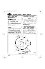
1. Using engine barring socket J 38587-A, or
equivalent, manually rotate engine in normal
rotation direction until pointer in flywheel
housing aligns with the valves 1 and 6 marks
on the flywheel and the No. 1 piston is at top
dead center on the compression stroke.
Valve lash must be set using the valve
adjustment marks on the engine flywheel, which
are at 30 degrees ATC. This ensures that the
lifter is on the camshaft base circle and not on the
brake ramp portion of the lobe.
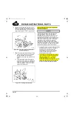
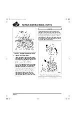
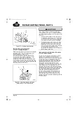
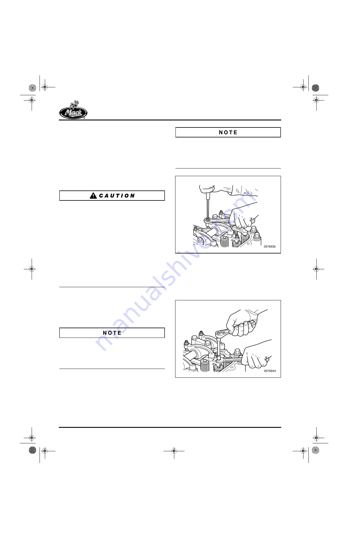
2. Loosen the rocker arm adjusting screw jam
nuts and back out the adjusting screws
several turns. ASET™ engine rocker arm
adjusting screws have a 5 mm internal hex
at the screw head.
For clarity, most of the illustrations in this section
show adjustments being performed without the
Jake brake units being installed. However, the
Jake units must be installed to correctly adjust the
inlet and exhaust valve lash.
552
Figure 552 — Loosening Exhaust Rocker Arm Locknut
and Backing Out Adjusting Screw
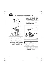
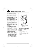
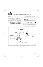
3. Loosen the No. 1 cylinder yoke adjusting
screw jam nuts for the exhaust valves. Yoke
adjusting screws used with the J-Tech™
brake have a 8 mm hex at the top of the
screw body.
553
Figure 553 — Loosening Valve Yoke Adjusting Screw
Locknut
5-111.bk Page 450 Monday, July 10, 2006 2:26 PM
Summary of Contents for ASET AC
Page 6: ...TABLE OF CONTENTS Page iii TABLE OF CONTENTS 5 111 bk Page iii Monday July 10 2006 2 26 PM...
Page 14: ...INTRODUCTION Page 1 INTRODUCTION 5 111 bk Page 1 Monday July 10 2006 2 26 PM...
Page 23: ...Page 10 NOTES 5 111 bk Page 10 Monday July 10 2006 2 26 PM...
Page 96: ...COMPONENT LOCATOR Page 83 COMPONENT LOCATOR 5 111 bk Page 83 Monday July 10 2006 2 26 PM...
Page 99: ...Page 86 NOTES 5 111 bk Page 86 Monday July 10 2006 2 26 PM...
Page 100: ...TROUBLESHOOTING Page 87 TROUBLESHOOTING 5 111 bk Page 87 Monday July 10 2006 2 26 PM...
Page 140: ...MAINTENANCE Page 127 MAINTENANCE 5 111 bk Page 127 Monday July 10 2006 2 26 PM...
Page 153: ...Page 140 NOTES 5 111 bk Page 140 Monday July 10 2006 2 26 PM...
Page 383: ...Page 370 NOTES 5 111 bk Page 370 Monday July 10 2006 2 26 PM...
Page 479: ...Page 466 NOTES 5 111 bk Page 466 Monday July 10 2006 2 26 PM...
Page 480: ...SPECIFICATIONS Page 467 SPECIFICATIONS 5 111 bk Page 467 Monday July 10 2006 2 26 PM...
Page 505: ...Page 492 NOTES 5 111 bk Page 492 Monday July 10 2006 2 26 PM...
Page 513: ...Page 500 NOTES 5 111 bk Page 500 Monday July 10 2006 2 26 PM...
Page 519: ...Page 506 NOTES 5 111 bk Page 506 Monday July 10 2006 2 26 PM...
Page 520: ...APPENDIX Page 507 APPENDIX 5 111 bk Page 507 Monday July 10 2006 2 26 PM...
Page 528: ...INDEX Page 515 INDEX Index fm Page 515 Monday July 10 2006 2 48 PM...
Page 535: ...Page 522 NOTES Index fm Page 522 Monday July 10 2006 2 48 PM...

