DESCRIPTION AND OPERATION
Page 71
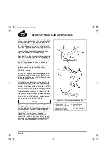
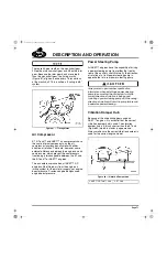
There are 45 gear teeth on the crankshaft gear,
90 teeth on the camshaft gear and 48 on the idler
gear. Because the idler gear has 3 more teeth
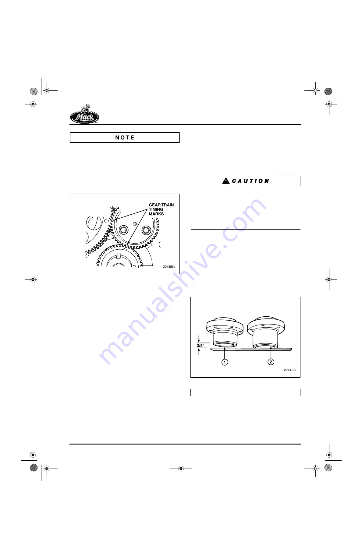
than the crankshaft gear, the timing marks
(Figure 81) align only once every 16 revolutions
of the crankshaft. This is called a “hunting tooth”
system.
81
Figure 81 — Timing Marks
Air Compressor
E7, E-Tech™ and ASET™ air compressors have
the same internal components, as the air
compressor functions equally well with either
direction of rotation. There are, however, some
external differences between the engines and air
compressors, which prevent the compressors
from being interchangeable between the E7 and
the E-Tech™ or ASET™ engines.
The air compressors used on all ASET™ AC
engines utilize filtered air from the engine air
intake system for their inlet air supply, not engine
boost pressure. Previous engine designs used
engine boost pressure.
Power Steering Pump
All ASET™ engines have the capability of driving
a power steering pump from either the front or
rear of the auxiliary shaft. Naturally, the direction
of rotation of a front power steering pump is
opposite that of a rear power steering pump.
Always refer to part number specification
information when installing a power steering
pump to ensure that the correct part with the
correct direction of rotation is being used.
Installing a power steering pump with the wrong
direction of rotation will result in pump failure and
inoperative power steering.
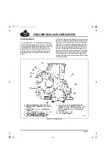
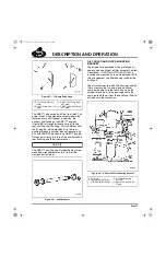
Vibration Damper Hub
Because of the wide timing gears used on
ASET™ engines, it is essential that the correct
vibration damper hub is used. The vibration
damper hub is 3/8 inch shorter than the E7 hub
(Figure 82) which is similar in appearance.
Always make sure the correct vibration damper is
used for the correct engine model.
82
Figure 82 — Vibration Damper Hub
1. ASET™/E-Tech™ Hub
2. E7 Hub
5-111.bk Page 71 Monday, July 10, 2006 2:26 PM
Summary of Contents for ASET AC
Page 6: ...TABLE OF CONTENTS Page iii TABLE OF CONTENTS 5 111 bk Page iii Monday July 10 2006 2 26 PM...
Page 14: ...INTRODUCTION Page 1 INTRODUCTION 5 111 bk Page 1 Monday July 10 2006 2 26 PM...
Page 23: ...Page 10 NOTES 5 111 bk Page 10 Monday July 10 2006 2 26 PM...
Page 96: ...COMPONENT LOCATOR Page 83 COMPONENT LOCATOR 5 111 bk Page 83 Monday July 10 2006 2 26 PM...
Page 99: ...Page 86 NOTES 5 111 bk Page 86 Monday July 10 2006 2 26 PM...
Page 100: ...TROUBLESHOOTING Page 87 TROUBLESHOOTING 5 111 bk Page 87 Monday July 10 2006 2 26 PM...
Page 140: ...MAINTENANCE Page 127 MAINTENANCE 5 111 bk Page 127 Monday July 10 2006 2 26 PM...
Page 153: ...Page 140 NOTES 5 111 bk Page 140 Monday July 10 2006 2 26 PM...
Page 383: ...Page 370 NOTES 5 111 bk Page 370 Monday July 10 2006 2 26 PM...
Page 479: ...Page 466 NOTES 5 111 bk Page 466 Monday July 10 2006 2 26 PM...
Page 480: ...SPECIFICATIONS Page 467 SPECIFICATIONS 5 111 bk Page 467 Monday July 10 2006 2 26 PM...
Page 505: ...Page 492 NOTES 5 111 bk Page 492 Monday July 10 2006 2 26 PM...
Page 513: ...Page 500 NOTES 5 111 bk Page 500 Monday July 10 2006 2 26 PM...
Page 519: ...Page 506 NOTES 5 111 bk Page 506 Monday July 10 2006 2 26 PM...
Page 520: ...APPENDIX Page 507 APPENDIX 5 111 bk Page 507 Monday July 10 2006 2 26 PM...
Page 528: ...INDEX Page 515 INDEX Index fm Page 515 Monday July 10 2006 2 48 PM...
Page 535: ...Page 522 NOTES Index fm Page 522 Monday July 10 2006 2 48 PM...


