50
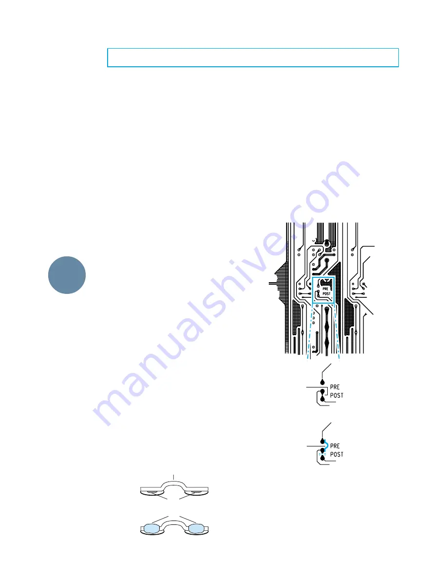
Figure 8: Modification I — Aux Send
BEFORE
cut here (A)
AFTER
add jumper (B)
APPENDIX C: Modifications
ADD-ONS
SPECS
ETC.
I. AUX Send mod
This modification changes the tap point of all
“pre” AUX sends from
post
-EQ to
pre
-EQ. It must
be done on each channel. For example, if you
have a 24•8, the modification must be done on
all 24 input channels.
See Figure 8. This modification takes place on
each channel strip in an area under the AUX 1/2
Pre/Post switch.
1.
Remove power cable.
2.
Cut the conductor at Point A.
3
. Add a jumper at Point B.
4.
Repeat for all input channels.
We have included step-by-step instructions for
five different 8•Bus console modifications.
Before we go any farther, consider that perform-
ing ANY modification will place your factory
warranty in jeopardy. Here is the Official Mackie
Statement:
Official Disclaimer
Any modification of any Mackie Designs
product must be done by a competent
electronic technician. Mackie Designs, Inc.,
accepts no responsibility for any damages or
injuries caused by any modification, regard-
less of the source of the modification
instructions or the qualifications of the tech-
nician performing them. In the case of such
damages, Mackie Designs may declare war-
ranty privileges void. BE CAREFUL!
To clarify…
These modifications are extremely easy, rela-
tive to what a real technician is used to doing.
However, they are extremely difficult and dan-
gerous for the inexperienced. If you’re not a
qualified, experienced technician, don’t even
think about considering the possibility of con-
ceiving of doing these mods yourself.
One of them (Mod V) actually changes the func-
tion of a switch so it no longer performs as labeled.
Ask around to find a decent repair/modifica-
tion shop that guarantees its own work in
writing (even then, your Mackie Limited War-
ranty can be in jeopardy). Better yet, wait until
the Warranty expires.
A note about adding jumpers during
these modifications
When a jumper or jumpers are called for, they
should NOT go into holes in the PCB. Rather,
they should be soldered to the flat, tinned area
around the hole (called a pad) and bowed
slightly over to the other pad (see Figure 7 be-
low). Make sure the ends of those jumpers do
not extend beyond the pad.
Figure 7
Holes
Jumper
Solder
BEFORE
AFTER
CAUTION
— These modification instructions are for use by qualified personnel only. To avoid electric shock, do not perform any
servicing other than changing the fuse unless you are qualified to do so. Refer all servicing and modifying to qualified personnel.


