Q u i c k S t a r t G u i d e
9
CONSOLE DATA
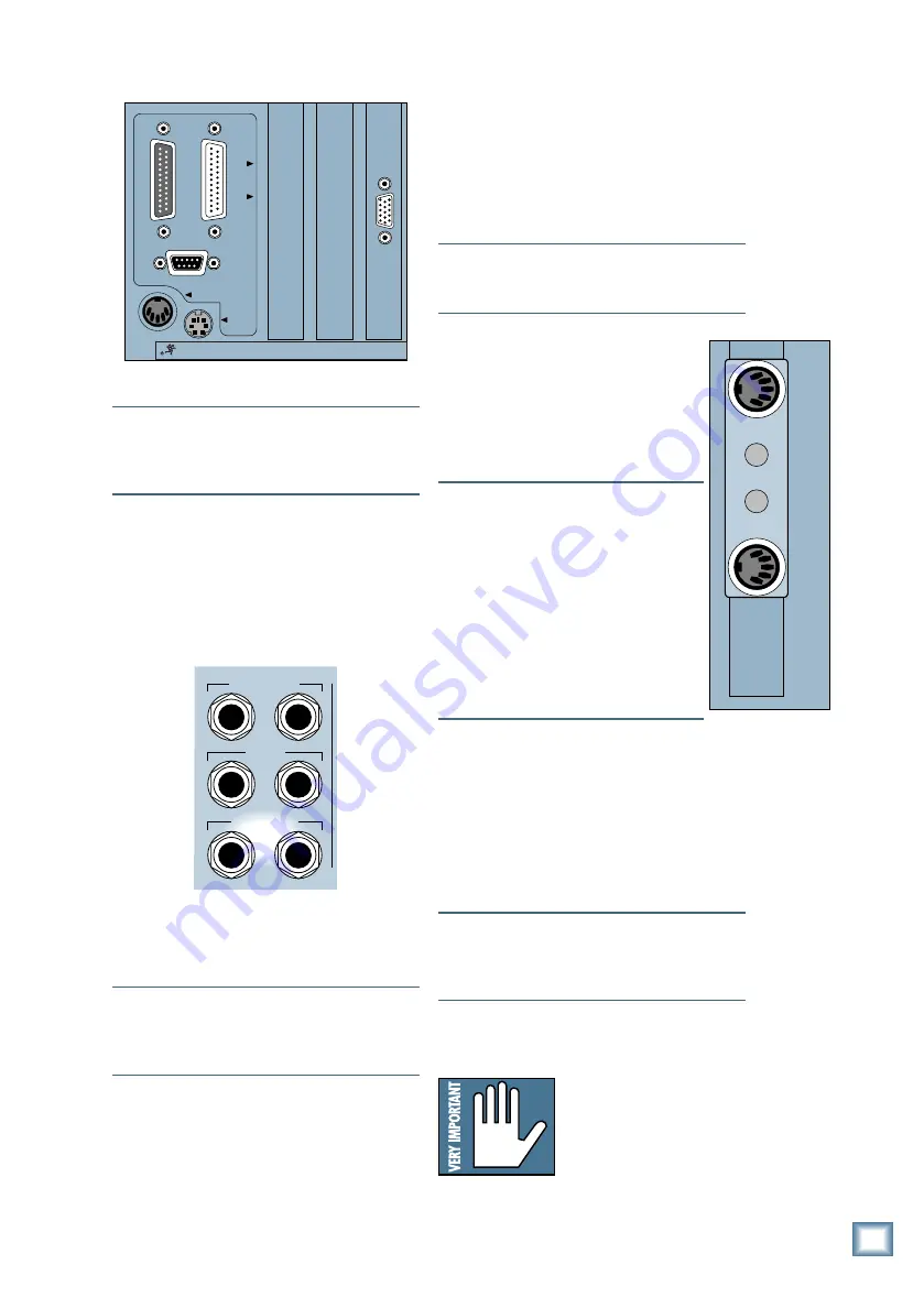
PARALLEL
VIDEO
SERIAL
KEYBOARD
MOUSE
CONCEIVED, DESIGNED, AND MANUFACTURED BY MACKIE DESIGNS INC • WOODINVILLE • WA • USA •
THE FOLLOWING ARE TRADEMARKS OR REGISTERED TRADEMARKS OF MACKIE DESIGN INC.: "MACKIE", "D
Note:
The video monitor must be a multi-sync
monitor or, if not, capable of at least a 72Hz
scan rate. We recommend using a 17-inch or
larger monitor for best results.
Now connect the audio inputs and outputs to
the console.
1. Using standard “guitar cord”-type cables
with 1/4" phone plugs, connect the Left and
Right CR NEAR FIELD outputs on the rear
panel of the Digital 8•Bus to the left and
right inputs of the power amplifier.
MASTER OUT
CR
MAIN
CR
NEAR FIELD
L R
L R
L R
2. Using heavy-gauge speaker wire appropriate
for the power of the amplifier, connect the
left and right outputs of the power amplifier
to the speaker inputs.
Note:
If you’re using powered monitors,
connect the Left and Right CR NEARFIELD
outputs directly to the line inputs on the
powered monitors.
3. To connect a recording deck to the Digital
8•Bus, it is necessary to have at least one of
the optional Tape I/O cards installed. For this
example, we’ll use an analog Tape I/O card.
This card has two 25-pin D-Sub connectors
for connecting the analog Tape I/O signals to
your tape deck.
If you are using the digital Tape I/O card,
refer to the Digital 8•Bus Owner’s Manual
(Appendix F) for connection information.
The connection on the other end of the cable
depends on your recording deck. It could be
any number of flavors, including Elco, 1/4"
phone plug, RCA phono plug, XLR, 25-pin
D-Sub, 3/4" garden hose, etc.
Note:
If you’re using a patch bay, place it
between the Digital 8•Bus and your tape
recorder.
Connections for MIDI
1. On the back of the Remote CPU, plug
the supplied dual output MIDI jack
adapter into the 9-pin D-Sub MIDI
connector. The output jack has standard
5-pin MIDI IN and OUT sockets on it.
Connect these to the MIDI IN and
OUT connectors on your recorder.
Note:
Most recorders require a MIDI
interface box to go between an external
MIDI control device such as the Digital
8•Bus, and its own MIDI I/O. Check
your recorder’s manual for more
information.
Note:
If you’re using more than one 8-
track recorder, you may need to match
your device ID with that of the Digital
8•Bus’ software. Please consult the
Digital 8•Bus Owner’s Manual and your
recorder’s manual for proper settings.
Optional Refreshments
1. Take a sip of coffee.
Power-Up
• Make sure the POWER switch on the
Remote CPU is off. Now plug the linecord
into an AC outlet properly configured for
your model.
Note:
The Remote CPU should be treated as
you would any computer. We recommend that
you use a UPS (Uninterruptible Power Supply)
and a surge protector on the AC line.
• Leave the POWER switch off while
connecting the peripheral equipment to the
console.
Caution:
Never connect or
disconnect anything except
microphone or line-level
inputs while the console is
powered up.
Tutorial Hookup — Let’s Get It Working
MIDI
OUT
MIDI
IN


