Q u i c k S t a r t G u i d e
27
Hookup for Tracking
Figure 8 shows a typical hookup for
tracking. Four microphones are connected to
channels 1–4 for vocals. Two of them are
condenser mics which require phantom power,
so the +48V PH switch is pushed in on those
channels. A vocal enhancer is connected to the
channel 1 INSERT jack to add a special effect
to the lead vocal.
Note:
Normally, you probably wouldn’t use in-
line effects on individual channels during
tracking. (We’re talking
effects
here, which is
not the same as dynamics, such as compression
and limiting, which would be okay to use
during tracking.) It’s usually best to get the
instrument or voice down on tape unaltered
during tracking, then add effects during
mixdown. But we thought you should know how
to do it anyway, just in case you have an
application that requires it.
Various instruments are connected to the
line inputs of channels 11–14, either directly
from their line-level outputs or through effects
boxes or direct boxes.
Each input from channels 1–24 is assigned
to a tape output, which can be connected to an
8-, 16-, or 24-track recorder. You can assign
any input (1–48), any return (FX 1–16, RET 1-8),
and Bus 1–8 to any unused tape out using the
ROUTE TO TAPE button in the Bus
Assignment Section.
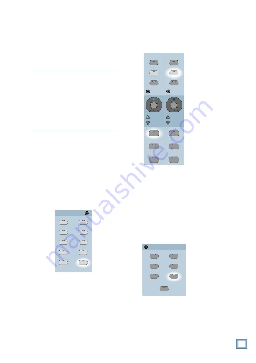
• Press ROUTE TO TAPE in the Bus
Assignment Section.
BUS 1
BUS 2
BUS 3
BUS 4
BUS 5
BUS 7
BUS 6
BUS 8
L-R
ROUTE TO
TAPE
ASSIGNMENT
ASSIGN
ASSIGN
ASSIGN
ASSIGN
ASSIGN
ASSIGN
ASSIGN
ASSIGN
ASSIGN
ASSIGN
• Press the SELECT button on the channel
you want to assign to a Tape Out.
• Press the ASSIGN button for the Tape Out
(1-24) you want to assign the selected
channel to. (In the following graphic,
channel 12 is assigned to Tape Out 13.)
13
37
12
36
ASSIGN
WRITE
ASSIGN
WRITE
REC/RDY
REC/RDY
SELECT
MUTE
SOLO
SELECT
MUTE
SOLO
Monitoring
Connect the outputs from the recorders to
the TAPE Inputs on the Digital 8•Bus. This
allows you to monitor the signal as it’s being
recorded (assuming your recorder has that
capability). To do this:
• Assign channels 25–48 (or whatever
channels are being used for tape returns) to
the L-R bus.
• In the Control Room Section, assign
MASTER L-R as the Control Room Source.
2 TRACK A
DIGITAL IN 1
2 TRACK B
DIGITAL IN 2
2 TRACK C
MASTER
L-R
CONTROL ROOM
MONO
Hookup for Multitrack Recording


