background image

11

CLIP

LEFT RIGHT

48v

POWER

STATUS

22

10

7

4

POWER

ON

TIP OU
RING R

FOR USE

(TIP =  S

DIRECT OUT WITH SIGNAL 

INTERRUPTION TO MASTER

OPTIONAL USES FOR I

INSERT ALL THE WAY IN TO

THE "SECOND CLICK"

MONO PLUG

120 VAC, 50/60 Hz,

35 WATTS

12 CHANNEL COMPACT INTEGRAT

CFX12

TAPE INPUT

Patch the outputs of your intermission en-

tertainment here. Any line-level mono or stereo
device can be used: tape, CD player, television
audio, etc. See 

BREAK SWITCH


 for more

information.

When connecting a mono device (just one

cord), you’ll need a “Y-splitter” RCA adapter. It
turns a mono output cord into two cords; so
both the left and right tape input jacks can be
patched. This adapter is widely available.

TAPE OUTPUT

Use these jacks to capture the entire perfor-

mance to tape. The signal at these jacks is the
main mix, after the 

MAIN INSERT


 but be-

fore the 

MAIN MIX

 Fader 

. The main mix

signal will be present at these jacks regardless
of the position of the 

MAIN MIX

 Fader.

PHONES

The stereo signal at these jacks is the same

as at the 

MAIN OUT


, but with two impor-

tant differences:

After the 

MAIN MIX

 Fader 

, the mix is

sent through the 

PHONES LEVEL


 control,

allowing you to set levels as desired, without
disturbing the main mix level.

When a channel’s 

SOLO PFL


 is engaged,

the main mix signal at this output will be re-
placed by the solo signal, allowing the engineer
to audition channels without disturbing the
main mix.

The stereo 

PHONES

 jack will drive any

standard headphones to very loud levels.
Walkperson-type phones can also be used with
an appropriate adapter.

Note:

 Please see the “Safety Instructions” on

page 2 for information on hearing protection.

EFX FOOT SWITCH

You can connect a normally-open foot switch

to this connector to duplicate the function of
the 

BYPASS


 switch, located in the 

EMAC

EFFECTS PROCESSOR


. Closing the switch

connection causes the 

EFX BYPASS

 indicator

to light and mutes the effects.

Note:

 When a foot switch is plugged into

the 

FOOT SWITCH

 jack, the 

BYPASS

 switch

is disabled.

Just like the 

BYPASS


 switch, this

affects only the internal 

EMAC EFFECTS

PROCESSOR

 and not any device plugged into

STEREO EFX RETURN 2


.

LAMP

This BNC-type connector will accept almost

any of the widely available 12VDC 0.5 amp
gooseneck lamps, made by Littlite

®

 and others.

If your work involves mixing in the back of
dark theaters, this lamp will likely become
your best friend.

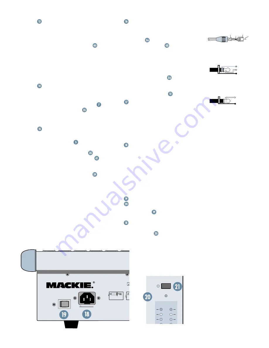
AC POWER INPUT

This IEC Socket is where you connect the

supplied AC linecord to provide AC power to
the CFX mixer. Plug the cord into a suitable
AC outlet, properly grounded and capable of
delivering adequate current.

If you happen to lose the AC linecord,

replacements are available at any office/
computer supply store.

POWER SWITCH

POWER STATUS

The 

POWER


 switch is located on the

rear panel, adjacent to the AC Power Input

. Push the side of the switch labeled “

ON

to turn the mixer on; you should see the

POWER STATUS


 LED glow in confirma-

tion. To turn the mixer off, push the switch the
other way. (Let’s all say a big collective “Duh.”)

SLEEVE

(SHIELD)

TRS HEADPHONE WIRING

TIP

(LEFT)

RING

(RIGHT)

TIP

SLEEVE

TIP

SLEEVE

RCA UNBALANCED WIRING

SLEEVE

(GROUND)

TIP

(HOT)

TS FOOTSWITCH WIRING

Summary of Contents for CFX 12

Page 1: ...O 40 50 5 5 U 60 10 SOLO PFL dB 30 20 10 O O 40 50 5 5 U 60 10 SOLO PFL dB 30 20 10 O O 40 50 5 5 U 60 10 SOLO PFL dB 30 20 10 O O 40 50 5 5 U 60 10 SOLO PFL dB 30 20 10 O O 40 50 5 5 U 60 10 SOLO PF...

Page 2: ...amplifiers that produce heat 9 Do not defeat the safety purpose of the polarized or grounding type plug A polarized plug has two blades with one wider than the other A grounding type plug has two bla...

Page 3: ...s like this Every feature on the CFX mixer has one of these numbers assigned to it Whenever a feature is mentioned described or illustrated its number will be right next to it Thank you for choosing a...

Page 4: ...Info 20 Warranty Service 20 Troubleshooting 20 Repair 21 APPENDIX B Technical Info 21 Specifications 21 Block Diagram 22 Contributors and Colophon 23 CFX MKII SERIES LIMITED WARRANTY 23 IMPORTANT SAFE...

Page 5: ...trip GAIN AUX EFX and Fader down 3 STEREO GRAPHIC EQ sliders centered 4 MASTER AUX and EFX SENDS and EFX RETURNS down 5 Channel strip EQ and PAN controls centered 6 Channel strip ASSIGN 1 2 and MUTE s...

Page 6: ...n up the MAIN MIX Fader to a comfortable listening level 5 If the overall mix has an equalization problem make adjustments to the STEREO GRAPHIC EQ If an individual channel is the problem use its EQ i...

Page 7: ...t Reverb Digital Delay Mono Power Amplifiers Digital Multitrack Recorder Guitar Effects Direct Box 5 6 7 8 9 10 11 12 13 14 15 16 20 19 18 17 2 1 1 2 R L R L R L R L 2 1 CHANNEL INSERTS STEREO EFX RET...

Page 8: ...3 MIC 4 MIC 5 MIC 6 MIC 7 MIC 8 At the risk of stating the obvious this is where you plug everything in microphones line level instruments effects headphones and the ultimate destination for your sou...

Page 9: ...signal enters the real world The XLR balanced outputs will add 6 dB when connected to balanced inputs thereby elevating signal from the noise floor by that amount The TRS balanced outputs offer the a...

Page 10: ...TRS outputs is post fader only so they cannot be used as traditional stage monitor cues They re in tended to patch into effects device inputs hence the name EFX See EFX 1 EXT and EFX 2 INT for more in...

Page 11: ...levels Walkperson type phones can also be used with an appropriate adapter Note Please see the Safety Instructions on page 2 for information on hearing protection EFX FOOT SWITCH You can connect a nor...

Page 12: ...ges from off through unity the center detent position on up to 15 dB of extra gain fully clockwise The line level stereo channels AUX knobs control a mono sum of the channel s stereo sig nals For inst...

Page 13: ...ou can also screw things up If you max the EQs on every channel you ll get mix mush not to mention driving your mix levels near or beyond clipping So equalize subtly use the left sides of the knobs cu...

Page 14: ...dependently of the rest of the mix SUB Faders SUB ASSIGN and MAIN MIX Fader will explain this further FADER Although the most self explanatory item on a mixer we ll explain it anyway The fader is the...

Page 15: ...results try to keep your peaks between 0 and 7 You may already be familiar with 4 4 dBu 1 23V and 10 10 dBV 0 32V operating levels Basically what determines the operat ing level is the relative 0 dB...

Page 16: ...e mixer via its TRS jacks and SUB ASSIGN sends it to the MAIN MIX Fader LEFT RIGHT SUB ASSIGN As discussed in ASSIGN the only way to get channel outputs to the main mix is via the sub mixes and this s...

Page 17: ...e EMAC EFFECTS PROCESSOR FOR THE IMPATIENT Set EFX 2 SEND and TO MAIN MIX at the center U mark As suming you have your basic mix up and run ning turn up the EFX 2 INT per channel This feeds in individ...

Page 18: ...ng pre delay and late reflections Tails are very warm with some additional high end reflections imitating the stone walls of a cathedral A very dramatic effect that works well with wind instruments su...

Page 19: ...a dramatic effect to vocals particularly group harmonies and choirs The channel s EFX 2 INT should be set halfway or higher Rate is adjust able from 0 5 Hz to 30 Hz Depth is adjustable from 0 to 100...

Page 20: ...S AND CONSIDERATIONS When setting up for a show oftentimes you are plugging into an AC power distribution sys tem you know nothing about You may even be faced with 2 wire outlets that are missing the...

Page 21: ...surance for all forms of cartage 8 We ll try to fix the mixer within five business days Once it is repaired we ll ship it back the same way in which it was received This paragraph does not neces saril...

Page 22: ...EFX BYPASS EFX FOOT SWITCH 5 VDC GLOBAL PHANTOM POWER WOODINVILLE EXIT BOTHELL MONROE EMAC DSP EFX LEVEL SET L R SOLO CONTROL ACTIVE LOW SOLO OFF SOLO ON SUB 2 OUT LEFT ASSIGN RIGHT ASSIGN LEFT ASSIGN...

Page 23: ...location within the boundaries of the USA G LOUD Technologies warrants all repairs performed for 90 days or for the remainer of the warranty period This warranty does not extend to damage resulting fr...

Page 24: ...Red Road NE Woodinville WA 98072 USA US and Canada 800 898 3211 Europe Asia Central and South America 425 487 4333 Middle East and Africa 31 20 654 4000 Fax 425 487 4337 www mackie com E mail sales m...

Reviews: