background image

15

 MAIN INSERT

These 

1

/

4

" jacks are for connecting serial

effects such as compressors, equalizers, de-
essers, or filters  . The 

INSERT

 point is after

the mix amps, but before the 

MAIN L-R MIX

fader.


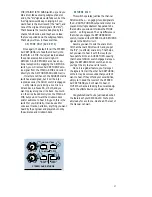
Insert cables must be wired thusly:

“tip”

This plug connects to one of the 
mixer’s Channel Insert jacks.

“ring”

tip

ring

sleeve

SEND to processor

RETURN from processor

(TRS plug)

Tip = send (output to effects device)
Ring = return (input from effects device)
Sleeve = common ground (connect shield to

 all three sleeves)

 MAIN OUTS

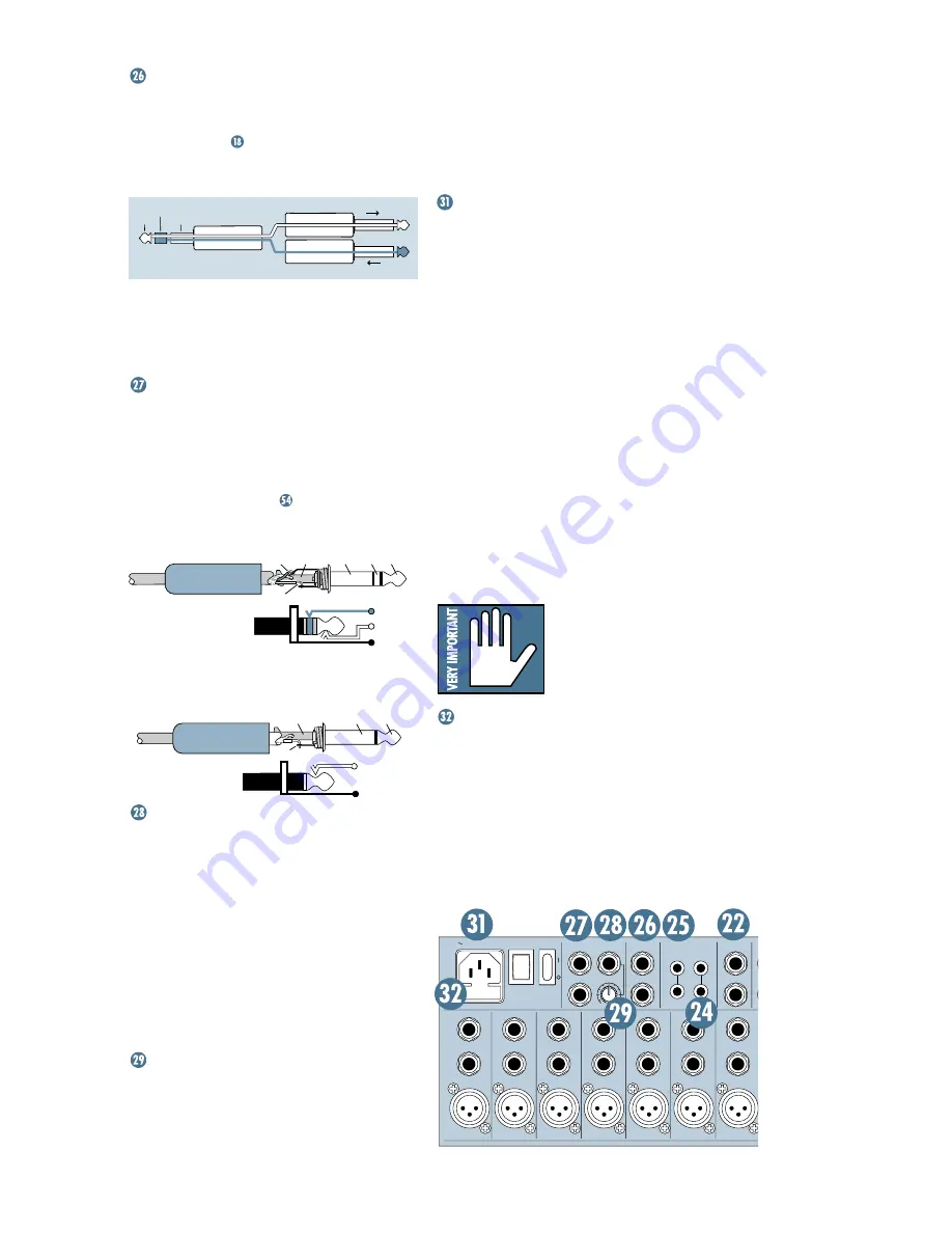
These 

1

/

4

" jacks are usually patched to the

inputs of your 2-track mixdown deck (unless
you’ve chosen to use the 

TAPE OUTPUT

 RCA

jacks), or to the house amplifier during live
sound sessions. 

To learn how signals are

routed to these outputs:


. To use these out-

puts to drive balanced inputs, connect 

1

/

4

" TRS

(Tip-Ring-Sleeve) phone plugs like this:

Tip = + (hot)
Ring = – (cold)
Sleeve = ground

To use these outputs to drive unbalanced

inputs, connect 

1

/

4

" TS (Tip-Sleeve) phone

plugs like this:

Tip = signal
Sleeve = ground

 MONO OUTPUT

It happens to everybody sooner or later:

The forces that govern your world will demand
a monaural output from your painstakingly-
created stereo panorama. The last thing you
want to do is start twirling all your carefully-
placed 

PAN

 settings to one side. What to do?

Stick a cord in this 

1

/

4

" jack, hand the other

end to Mr. Mono, and you’re done. He’s got his
mono mix and you’ve still got your stereo mix.
The 

MONO 

output is nothing more than a mix

of the left and right 

MAIN MIX

.

 MONO LEVEL

So, Mr. Mono comes running back, scream-

ing about the mono mix being so loud that his
camcorder is melting. Just reach for this knob
and turn it down a bit. Just the thing for send-

ing mono signals to mic inputs like camcorders,
telephone interface boxes, even answering
machines. With the pot all the way up (fully
clockwise), you’ll have 6dB of extra gain with
unity gain halfway between the one and two
o’clock positions.

 POWER CONNECTION

Just in case you lose the cord provided with

the CR1604-VLZ, its power jack accepts a stan-
dard 3-prong IEC cord like those found on
most professional recorders, musical instru-
ments, and computers. At the other end of our
cord is — get this — a plug! Not a black cube
or, as we’re fond of calling them, a “wall wart.”
We did this for some very good reasons:

The CR1604-VLZ has sophisticated power

requirements that a wall wart cannot provide.
Wall warts are inconvenient, fragile, radiate huge
hum fields, hog extra jacks on your power strip
and get in the way. If you lose a wall wart, you’re
in trouble, but if you lose the CR1604-VLZ’s power
cord, you can get a new one at any electronics,
music, or computer store. You can even buy them
at Radio Shack

®

 (part # 278-1257).

Plug the CR1604-VLZ into any standard

grounded (3-pin) AC outlet or into a power
strip of proper voltage.

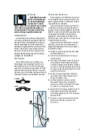
WARNING: Disconnecting
the plug’s ground pin can
be dangerous. Please
don’t do it.

 FUSE

The CR1604-VLZ is fused for your (and its

own) protection. If you suspect a blown fuse,
disconnect the power cord, pull the fuse drawer
out (located just below the cord receptacle)
and replace the fuse with a 1A SLO BLO, 5x20mm,
available at electronics stores or your dealer
(or a 500mA [0.5 amps] SLO BLO 5x20mm if
your CR1604-VLZ is a 220V-240V unit).

SLEEVE

TIP

SLEEVE

TIP

RING

RING

TIP

SLEEVE

RING

SLEEVE

TIP

TIP

SLEEVE

TIP

SLEEVE

O

O

+6

PHANTOM

POWER

    120 VAC 50/60 Hz 20W

315mA/250V SLO-BLO

16

15

14

13

12

11

10

MIC 16

INSERT

INSERT

INSERT

INSERT

INSERT

INSERT

INSERT

MIC 15

MIC 14

MIC 13

MIC 12

MIC 11

MIC 10

C-R OUTS

MAIN INSERT

TAPE

TAPE

MAIN OUT

R

L

MONO

R

L

R

L

R

L

R

L

BAL/UNBAL

BAL/UNBAL

INPUT

OUTPUT

BAL
UN-
BAL

BAL
UN-
BAL

BAL
UN-
BAL

BAL
UN-
BAL

BAL
UN-
BAL

BAL
UN-
BAL

BAL
UN-
BAL

LINE

LINE

LINE

LINE

LINE

LINE

LINE

TO REDUCE THE  RISK OF

FIRE REPLACE WITH SAME 

TYPE FUSE AND RATING

CAUTION:

Summary of Contents for CR1604-VLZ

Page 1: ...O O 15 U 15 15 U U 15 15 12k HI MID 80Hz LOW CUT 75 Hz 18dB OCT LOW U O O 15 3 MUTE U O O 15 U 15 15 U U 15 15 12k HI MID 80Hz LOW CUT 75 Hz 18dB OCT LOW U O O 15 4 MUTE U O O 15 U 15 15 U U 15 15 12...

Page 2: ...e connected to a power supply only of the type described in these operation instructions or as marked on this Mackie product 8 Power Cord Protection Power supply cords should be routed so that they ar...

Page 3: ...on these channels 15 Play like a madman and sing like a canary It s your first mix READTHISPAGE Please write your serial number here for future reference i e insurance claims tech support return autho...

Page 4: ...GAIN 10 U 60 10dB 40dB 10dBV L R L R L R L R L R L R L R L R L R L R L R L R L R L R L R L R MAX dB 30 20 10 O O 40 50 5 5 U 60 10 O O O O O O O O O O O O O O O O O O O O O O O O O O O O O O O O dB 30...

Page 5: ...of you accustomed to the original classic CR 1604 do not be daunted by all the new features we added them just for you Asterisked items indicate features that we ve added to the New Improved CR1604 V...

Page 6: ...L L L R L R TAPE OUT TAPE IN 16 15 14 13 12 11 10 9 8 7 6 5 4 3 2 1 3 2 1 Guitar Effects Drum Machine Keyboard or other line level input Stereo EQ w Compressor out in out in Mono in stereo out Reverb...

Page 7: ...L AUX SENDS BAL UNBAL SUB OUTS BAL UNBAL Guitar Effects Drum Machine Keyboard or other line level input Keyboard or other line level input Stereo Power Amplifier Right PA Speaker Left PA Speaker CD Pl...

Page 8: ...OUT BAL UNBAL MAIN OUT BAL UNBAL AUX SENDS BAL UNBAL SUB OUTS BAL UNBAL Keyboard or other line level input Stereo Power Amplifier CD Player Stereo Compressor Mono in stereo out Reverb Digital Delay M...

Page 9: ...They can be in stalled in either of two depths mixer s surface flush with the rack rails like ordinary rackmount equipment or mixer s surface sunken into the rack to protect the knobs from being bumpe...

Page 10: ...ted from these inputs If you wire your own connect them like this 2 2 3 1 1 SHIELD COLD HOT SHIELD COLD HOT 3 SHIELD COLD HOT 3 2 1 Pin 1 ground or shield Pin 2 positive or hot Pin 3 negative or cold...

Page 11: ...can be very handy when you are inserting a signal that is very hot or you want to add a lot of EQ gain or both Without this virtual pad a scenario like that might lead to channel clipping INSERT Thes...

Page 12: ...9 LINE input as we just discussed Hot tip To feed an 8 track deck with 4 sub outputs simply use Y cords SUB OUT 1 feeds tracks 1 and 5 2 feeds 2 and 6 3 feeds 3 and 7 and 4 feeds 4 and 8 Tracks in rec...

Page 13: ...uts To wire your own cables Double Busing How on earth do you get four jacks to feed eight tracks To feed an 8 track deck with only four SUB OUTS simply use four Y cords SUB OUT 1 feeds tracks 1 and 5...

Page 14: ...n until you ve put the phones on Then turn it up slowly Why Engineers who fry their ears find themselves with short careers TAPE OUTPUT These unbalanced RCA jacks tap the MAIN MIX outputs to make simu...

Page 15: ...the pot all the way up fully clockwise you ll have 6dB of extra gain with unity gain halfway between the one and two o clock positions POWER CONNECTION Just in case you lose the cord provided with the...

Page 16: ...D is actually a yellow voltmeter telling you that the phantom power takes time to ramp itself down to zero volts So if you ve turned phantom power off to connect something to the mic in puts wait unti...

Page 17: ...owing you to use the subgroup faders as a master control for those channels The sixteen channel strips look alike and function identically The only difference is that the eight on the left have DIRECT...

Page 18: ...LEVEL SET PFL is also the preferred mode for SR sound reinforcement or live sound to preview channels before they are let into the mix It won t give you stereo placement but will give you signal even...

Page 19: ...ference to these LEDs write this on the back of your hand name color flickering glowing 20 SOLO green signal is present channel is soloed OL MUTE red channel is clipping channel is muted MUTE Engaging...

Page 20: ...uit Nothing but the best for you We recommend that you use LOW CUT on ev ery sound source except kick drum bass guitar bassy synth patches or recordings of earth quakes These aside there isn t much do...

Page 21: ...signals to follow the level of the dry PAN AUX 3 1 2 EQ 5 4 6 5 6 SHIFT PRE TRIM 1 SOLO L R 3 4 1 2 OL 20 U O O 15 U O O 15 U O O 15 U 15 15 U 15 15 800 2k 200 8k U 15 15 12k HI MID 80Hz LOW CUT 75 H...

Page 22: ...em out at a different rate than the other channels You don t want to try that with seven hands or seven fin gers so just un assign these channels from L R reassign them to subgroup 1 2 engage the AS S...

Page 23: ...pedevicewithwimpyoutputlevels AftertheTAPE IN level isdetermined thestereo tapesignalcanbesenttoeitheroftwoplaces the MAIN L R MIXortheSOURCEmatrix TAPE TO MAIN MIX Engaging this switch is just like e...

Page 24: ...Level Setting Procedure Push in the MODE switch in the output section LEVEL SET PFL mode the LEVEL SET LED will light When the solo MODE switch is engaged it s in LEVEL SET PFL mode the mode you must...

Page 25: ...are at them unless you want to AUX TALK First of all there is no particular alliance between AUX SEND 1 and AUX RETURN 1 They re just numbers They re like two com plete strangers both named Fred Sends...

Page 26: ...SEND 1 master and TO AUX SEND 2 feeds AUX RETURN 2 to AUX SEND 2 master They are off when turned fully down deliver unity gain at the center detent and can provide up to 15dB of gain turned fully up...

Page 27: ...used for voice over tracks narration anything you want heard by the engineer and players but not by the audience and mixdown deck RETURNS SOLO This switch operates just like the channel SOLO switches...

Page 28: ...ls 6 AddajumperfromthesquarepadatpointB tothesquarepadatpointC 7 Repeatforeachchannelyouwishtomodify 8 Checkyourworkverycarefully themputthe bottomcoverbackthewayyoufoundit You redone UL Warning CAUTI...

Page 29: ...ead of post MAIN L R MIX fader Youcanaccomplishthesameresultthatthis modificationprovidesbyusingtwostandard1 4 tip sleeve jumpercables pluggedintotheMAIN INSERT L and R to thefirst click and the other...

Page 30: ...EFX TO MON SOLO TO SOLO LED SIP L SIP R PFL SOLO MACKIE CR1604 VLZ SIGNAL FLOW 16 41097 VSD DF CR PHN L CR PHN R SOLO RELAY ASSIGN TO MIX MAIN MIX INSERT FADER R MAIN MIX MONO OUT MAIN MIX LEFT OUT TA...

Page 31: ...MAIN MIX SUBMASTERS to A A to A to D from Main Mix Subs and Tape In 0dB 0dB D 10dB up OUTPUT 0dB SOURCE Matrix MIX LEVEL CONTROL ROOM PHONES C B 0dB From B 10dB up Channel SEND AUX MIX AUX 1 2 Master...

Page 32: ...hm termination 129 5dBm unweighted Common Mode Rejection CMR Mic in to Insert Send out max gain 1kHz better than 80dB Maximum Levels Mic in 14dBu All other inputs 22dBu Main Mix 1 4 TRS outputs 28dBu...

Page 33: ...rom your whatever Power Ourfavoritequestion IsthePOWER switchon Check the fuse REPAIR Service for the U S version of the CR1604 VLZ is only available from Mackie Designs located in sunnyWoodinville Wa...

Page 34: ...The band of frequencies that pass through a device with a loss of less than 3dB expressed in Hertz or in musical octaves Also see Q bus An electrical connection common to three or more circuits In mi...

Page 35: ...ratio of 1000V 1V 60dB When one of the terms in the ratio is an agreed upon standard value such as 0 775V 1V or 1mw the ratio becomes an absolute value i e 4dBu 10dBV or 0dBm delay In sound work delay...

Page 36: ...e the units called parametrics and graphics and notch filters A lot of how we refer to equalization has to do with what a graph of the frequency re sponse would look like A flat response no EQ is a st...

Page 37: ...nd If you have noise in your system due to technical grounding problems check your manual for wiring tips or call technical support Never disable the safety ground to reduce noise problems ground loop...

Page 38: ...sed to combine various audio signals into a common output Different from a blender which combines vari ous fruits into a common libation monaural Literally pertaining to or having the use of only one...

Page 39: ...y damaged Check the manufacturer s recom mendations and be careful phasing A delay effect where the original signal is mixed with a short 0 to 10 msec delay The time of the delay is slowly varied and...

Page 40: ...usually made reverberation is considered to be a dif fuse continuously smooth decay of sound whereas echo is a distinct recognizable repeti tion of a word note phrase or sound Reverberation and echo c...

Page 41: ...Sometimes called mono or unbalanced plugs or jacks A 1 4 TS phone plug or jack is also called a standard phone plug or jack unbalanced An electrical circuit in which the two legs of the circuit are n...

Page 42: ...ck or plug is connected tip to left ring to right and SLEEVE TIP TIP SLEEVE TIP SLEEVE Figure C TS Plug sleeve to ground earth Mackie mixers do not directly accept 1 plug type stereo microphones They...

Page 43: ...op in a circuit change the input routing of the signal or serve other functions Mackie uses switches in the channel insert and bus in sert jacks input jacks and AUX returns We also use these switches...

Page 44: ...t the signal you are tapping from the mixer That will affect the internal signal MACKIE STEREO INPUTS AND RETURNS Mono Stereo Whatever Stereo line inputs and stereo AUX returns are a fine example of t...

Page 45: ...r the outputs of both unbalanced and balanced circuits Remember Only mult or Y an output into sev eral inputs If you need to combine several out puts into one input you must use a mixer not a mult or...

Page 46: ...y to ex ternal noise specifically hum and buzz Because a balanced system is able to minimize noise it is the preferred interconnect method especially in cases where very long lengths of cable are bein...

Page 47: ...D12 D112 and many others If you are fortunate enough to own any tube condenser microphones such as the AKG C12 Neumann U47 or U67 these microphones may be connected in a phantom powered system and wi...

Page 48: ...t the electrician uses the star ground system for the safety grounds in your electrical system All of the audio system grounds should terminate at the same physical point No other grounds may come in...

Page 49: ...ry some ground lifter adapters and use them only when you have to plug into an ancient two wire outlet 9 If you bundle your cables together don t bundle AC wiring and audio wiring to gether Bundle the...

Page 50: ...O O 15 U O O 15 U O O 15 U O O 15 U O O 15 U O O 15 U O O 15 U O O 15 U O O 15 1 MUTE U O O 15 U 15 15 U U 15 15 12k HI MID 80Hz LOW CUT 75 Hz 18dB OCT LOW U O O 15 2 MUTE U O O 15 U 15 15 U U 15 15 1...

Page 51: ...6 SHIFT TRIM TRIM TRIM TRIM TRIM TRIM TRIM TRIM LAMP 12V 0 5A TAPE IN SOLO RUDE SOLO LIGHT C R PHONES SUBS 3 4 SUBS 1 2 MAIN MIX SOURCE TAPE TAPE TO MAIN MIX MAIN L R MIX RIGHT 1 2 3 4 LEFT RIGHT LEF...

Reviews: