D8B Manual • Chapter 3 • page 67
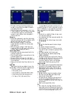
Link Option controller actions. There are eight
Network Channels that are not unlike TV channels
via Ethernet, where the console has a unique Device
Name (like 'Jolene' or 'Spike') and after setting the
Device Name and assigning one of the eight Network
Channels, the console may then join the party.
Consoles are normally linked audio-wise via
the ALT I/O 1–8 card slot where audio buses are
configured to be transferred from a slave console
to a master console for further mix processing. If
using the buses for digital audio, all allowances
for word sync must be made (both consoles need
to be clocked from the same source).
Note:
All of these Ethernet messages are
broadcast from any given control surface that is
on-line and transmitting or receiving. Updating
only occurs after the connection is established and
the console linking parameters are modified.
Another Note:
All D8Bs in a network must
have a unique IP address. See “FTP Server” on
page 71 for more info.
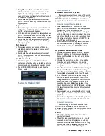
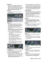
Network Channel
• Each Digital 8•Bus assigned to the same Network
Channel is linked according to the functions
selected in the Console Linking options.
• Communication between devices is dependent on
common network channel numbers. All devices
assigned to Network Channel 1 communicate
together and act as one console across the
selected Console Linking options. All devices on
Network Channel 2 communicate; all devices on
Network Channel 3 communicate; etc.
• Communication between all devices sharing a
common Network Channel is bidirectional on
common Link Option selections.
Local Mixer Name
• This simply allows the D8B to be given a unique
name for identification purposes across the network.
Alt I/O 1–8
• This provides for the routing of the audio signals
from Aux 1–12, Bus 1–8, or L/R output through
any I/O card installed in the Alt I/O slot.
Console Linking
• This provides the selection of control signals that
are sent or received on the Ethernet connection.
• When multiple D8Bs are linked together via their
individual Ethernet connections, they
communicate and respond according to the
selections in the Link Options list.
• Whichever parameters are selected are
transmitted and received across the network on
two or more D8Bs.
• Whichever parameters are not selected act
independently on each individual D8B.
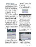
Console Linking options are enabled and
disabled according to what control surface actions
you want to have linked on two or more consoles
assigned to the same Network Channel.
•
Fader Banks:
This option provides for bank
selection across the network from any Digital 8•Bus
sharing a common Network Channel number.
•
Aux Strip:
This option links the selection of any
aux bus across the network. For example, if Aux 1
is selected on any networked Digital 8•Bus console,
it will be selected on all networked Digital 8•Bus
consoles with Aux Strip selected.
•
Bus Assign:
This links the BUS ASSIGN selection
across the network. For example, selecting Bus 1–8,
L–R, or Route to Tape in the ASSIGNMENT section
selects that assignment status in each networked
D8B with Bus Assign selected. This allows the
ASSIGN buttons to function identically on each D8B.
•
Cue Controls:
This links the Phones/Cue selection
across the network. For example, selecting any
parameter in the PHONES/CUE MIX 1 section
selects that parameter in each networked D8B with
Cue Controls selected.
•
Solo Logic:
This links the SOLO/STUDIO
selection across the network. For example,
selecting any solo or studio status in the SOLO/
STUDIO section selects that status in each
networked D8B with Solo Logic selected.
•
Speakers:
This links the Speaker selection across
the network, including NEAR FIELD, MAIN,
MONO, and DIM.
•
Sample Rate:
This links the sample rate setting
across the network. Selection of a sample rate
status on any networked Digital•8 Bus sets the
sample rate on the others with Sample Rate
selected. This link syncs the sample rate setting
but not the source setting (Apogee Clock Internal
or Word Clock setting). Word clock connections
must still be made using real live cables.
•
Automation:
This links the automation control
across the network. For example, enabling
automation by selecting ALL in the AUTOMATION
section, enables ALL automation in each networked
D8B with Automation selected.
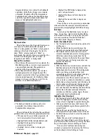
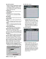
Digital I/O
The Digital I/O setup window allows you to
make input and output settings for the I/O cards
that are installed in the Tape In/Out card slots.
The D8B automatically senses the card configura-
tions and provides selection and patching options
accordingly.
Summary of Contents for d8B V5.1
Page 1: ...OWNER OWNER S MANUAL S MANUAL...
Page 9: ...D8B Manual Chapter 1 page 3 Chapter 1 Getting Ready...
Page 27: ...D8B Manual Chapter 2 page 21 Chapter 2 Where Is It...
Page 47: ...D8B Manual Chapter 3 page 41 Chapter 3 What s On TV...
Page 101: ...D8B Manual Chapter 4 page 95 Chapter 4 Applications...
Page 147: ...D8B Manual Appendices page 141 Appendices...
Page 198: ......


