D8B Manual • Chapter 3 • page 47
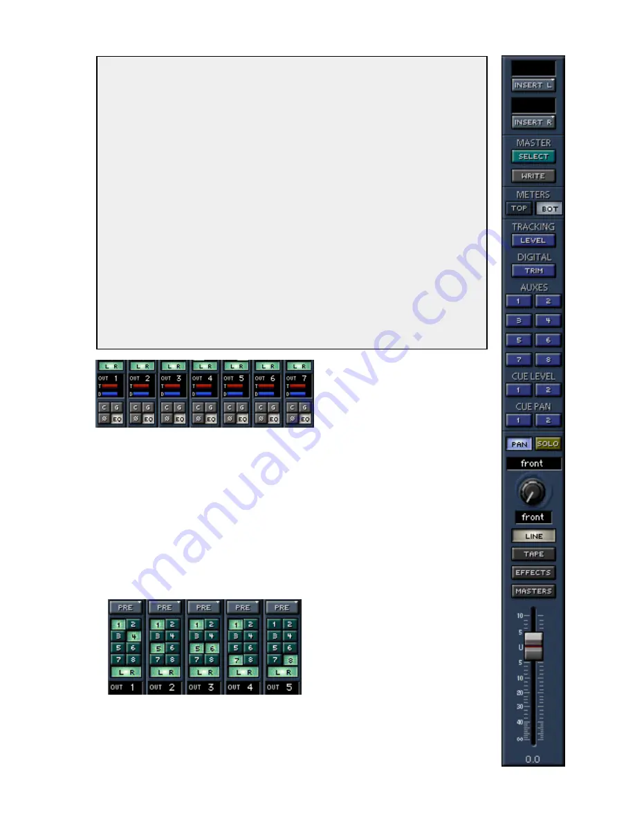
• Any channel can be sent to any number of tape
outputs by simply selecting multiple tape outputs:
however, only the last selected output is displayed
in the OUT window.
• No two channels can be assigned to the same tape
output. To sum channels to an output, assign
them to a bus, then route the bus to a tape out.
BUS and L/R Output Assignments
• Highlight any BUS out 1–8 to route the channel to
the selected bus.
• Highlight the L/R button to route the channel to
the Main L/R mix output.
• Click and hold on any BUS or L/R button, then
sweep across adjacent channels to assign the
selected bus output to multiple channels.
• To assign multiple channels to a
mono or stereo set of tape outs,
assign them to buses, or a pair of
buses, then route the buses to the
tape output(s).
• Stereo pairing is selected by
assigning a channel to any odd/
even bus pair (1/2, 3/4, 5/6, 7/8,
L/R, etc.) In this case, the PAN
control positions the channel
between the bus pairs.
The Master Strip
Master Fader
• Controls the Master L/R Mix level.
• Ideally set at unity gain. Control-
click anywhere in the fader throw
to automatically set the fader to
unity.
• Click anywhere in the fader throw
to instantly snap to that level.
MASTERS, EFFECTS, TAPE, AND
LINE buttons
These are the on-screen fader bank
selectors.
• LINE is Fader Bank 1
• TAPE is Fader Bank 2
• EFFECTS is Fader Bank 3
• MASTERS is Fader Bank 4
• HUI is Fader Bank 5 (only
available when HUI mode is active)
The Feedback Loop
Caution
Caution
Caution
Caution
Caution: When Bank to Outputs is selected from the TAPE IN bank—or anytime you assign
to a tape track from a tape return channel, then monitor the correlating fader—there is
potential for a nasty feedback loop. To create the feedback loop:
• Select the TAPE IN bank.
• Place the multitrack in record-ready.
• Assign a channel to its correlating multitrack input (Channel 25 to Tape Output 1, Channel
26 to Tape Output 2, etc.)
• Slowly raise the Level to Tape V-Pot—or if you’re in Faders to Tape mode, raise the
level of the TAPE bank channel fader—correlating to the tape track (Channel 25, 26,
etc.)
• Watch the nasty feedback loop on the meter bridge. You might not even be able to hear
the loop, but it’s there.
• Finally, try to never do that again!
Note
Note
Note
Note
Note: This phenomenon is not specific to the D8B OS; it’s just the way interconnecting gear
works. To eliminate the possibility of a feedback loop is to rob creative flexibility from the
system. We all learn to avoid creating feedback loops in our working environment. But it
helps to be alerted to the possibility from time to time.
Summary of Contents for d8B V5.1
Page 1: ...OWNER OWNER S MANUAL S MANUAL...
Page 9: ...D8B Manual Chapter 1 page 3 Chapter 1 Getting Ready...
Page 27: ...D8B Manual Chapter 2 page 21 Chapter 2 Where Is It...
Page 47: ...D8B Manual Chapter 3 page 41 Chapter 3 What s On TV...
Page 101: ...D8B Manual Chapter 4 page 95 Chapter 4 Applications...
Page 147: ...D8B Manual Appendices page 141 Appendices...
Page 198: ......


