D8B Manual • Chapter 3 • page 73
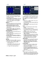
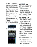
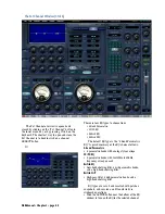
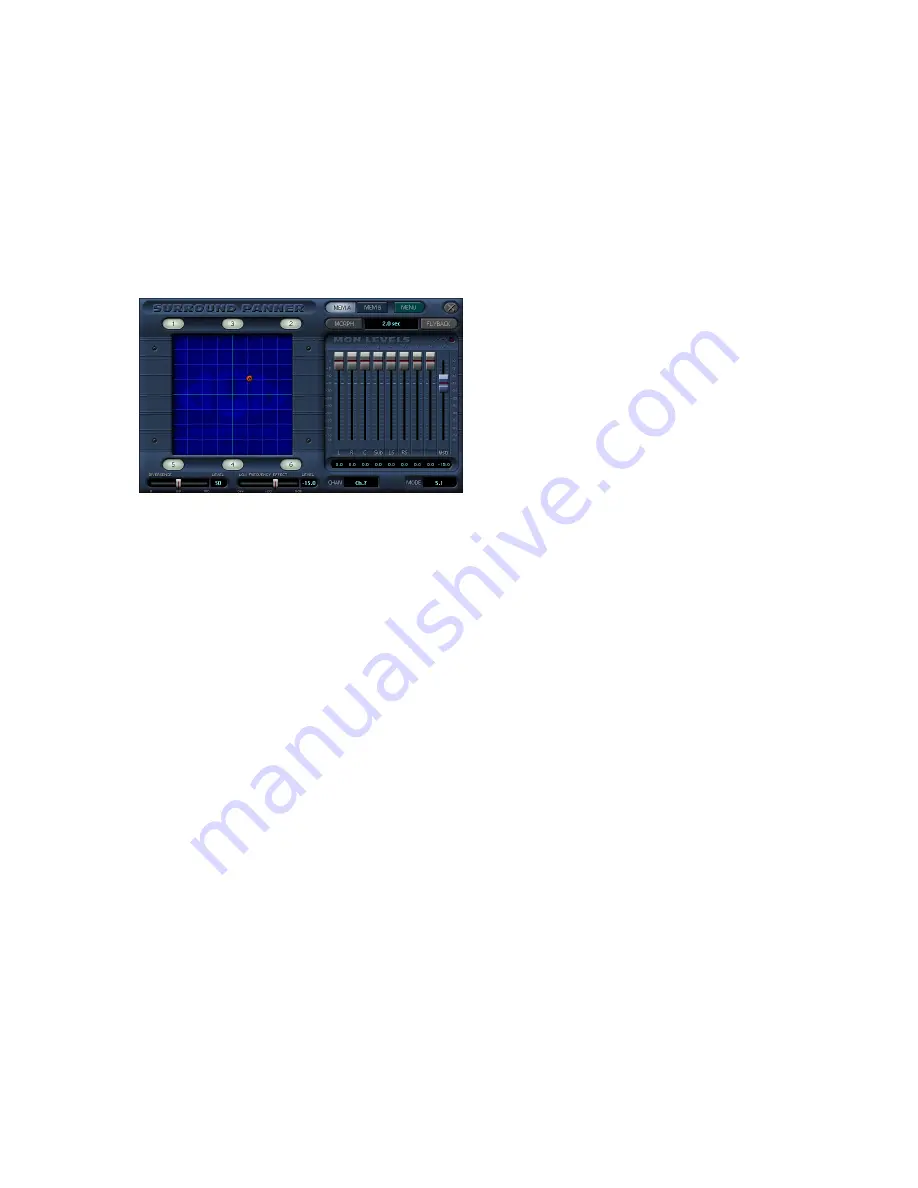
The Surround Window (Ctrl+3)
The surround window offers precise control
over image positioning in any mixing panorama
along with individual subwoofer level and depth of
center control.
Surround position control is available from
the control surface by using the individual Chan-
nel pan for L/R positioning and the Master Pan V-
Pot as the selected channel’s front/rear position
control. The control surface can perform surround
pan positioning using the Etch-A-Sketch
®
(Etch-
A-Mix) approach.
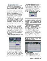
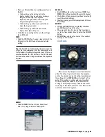
Surround Panner
• Simply drag the colored ball to position a channel
anywhere in the surround panorama.
• The top of the pan grid represents the front
speakers.
• The bottom of the pan grid represents the rear
speakers and the subwoofer.
• The subwoofer (Bus 4) is not affected by pan, but
in the case of LCRS, Bus 4 is the rear (surround)
panned bus output.
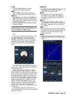
Monitor Levels
• When a surround mode other than stereo is
selected, the Monitor Levels faders appear in the
MON LEVELS box. Each fader corresponds to an
analog surround output at Buses 1-8.
• A Master fader controls the overall output level of
the eight surround outputs. The SPEAKER
LEVEL V-Pot in the D8B Control Room section
also controls the Surround Master Monitor fader
(when in a surround mode).
• The Monitor Levels affect the signal at the analog
Bus 1-8 outputs. They do not affect the signal at
the ALT 1-8 outputs when Bus 1-8 is assigned to
them. This allows you to fine tune your surround
sound monitoring speaker system without
affecting the digital surround output.
• Once the Monitor Levels are set, you can lock the
monitor level settings by clicking the MENU
button and choosing Lock Monitor Levels. The
LOCKED LED illuminates when the Monitor
Levels are locked. This allows you to calibrate
your setup for any number of standard reference
levels.
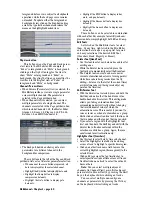
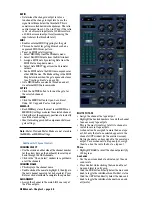
Flyback
• Adjust surround position as usual, by dragging the
red or green ball. However, when FLYBACK is
selected, the ball (surround position) immediately
snaps (flies) back to its original position once the
mouse button is released.
Output Assignment/Speaker Icons
• Toggles channel sends to individual speakers
within the surround system, between on and off.
• Click the desired speaker position to include it in
the channel’s surround pan position.
Pan Position (MEM A)
• Selected by clicking the MEM A button.
• Represented by the green ball in the Surround
Panner.
• Acts as a retrievable surround pan, divergence
level, and sub-effect level preset that is instantly
recalled when MEM A is clicked.
Pan Position (MEM B)
• Selected by clicking the MEM B button.
• Represented by the red ball in the Surround
Panner.
• Acts as a retrievable surround pan, divergence
level, and sub-effect level preset that is instantly
recalled when MEM B is clicked.
Morph
• Activated by clicking the MORPH icon.
• Automatically pans between the MEM A and
MEM B surround positions, divergence level, and
sub-effect level.
Morph Time
• Controls the amount of time it takes for the
MORPH process to move between the two preset
positions (MEM A and MEM B).
• Can be adjusted between 1 and 121 seconds.
Divergence
• This control spreads (from the Center to the Left
and Right) the channel surround pan position in
the front half of the surround panorama.
• The resultant moves can be recorded into automation.
Divergence Meter
• This display indicates the width of the center
image from 0 (Center) to 100 (Left and Right
only—phantom center channel).
• 50 is an even level distribution among L, C, and R.
Low Frequency Effect
• Acts as an individual channel level control to the
subwoofer output.
• The number four speaker icon controls the
subwoofer on and off status (except LCRS).
• Since low frequencies are omnidirectional,
individual channel sends to the subwoofer are not
controlled in the surround pan positioning grid.
Their sends to the subwoofers are adjusted by the
Low Freq Effect fader.
• The fader control attenuates from 0.0 (full level)
to –100 (off).
• The level may be further boosted or attenuated at
the Bus 4 fader for the entire subwoofer output.
Summary of Contents for d8B V5.1
Page 1: ...OWNER OWNER S MANUAL S MANUAL...
Page 9: ...D8B Manual Chapter 1 page 3 Chapter 1 Getting Ready...
Page 27: ...D8B Manual Chapter 2 page 21 Chapter 2 Where Is It...
Page 47: ...D8B Manual Chapter 3 page 41 Chapter 3 What s On TV...
Page 101: ...D8B Manual Chapter 4 page 95 Chapter 4 Applications...
Page 147: ...D8B Manual Appendices page 141 Appendices...
Page 198: ......


