32
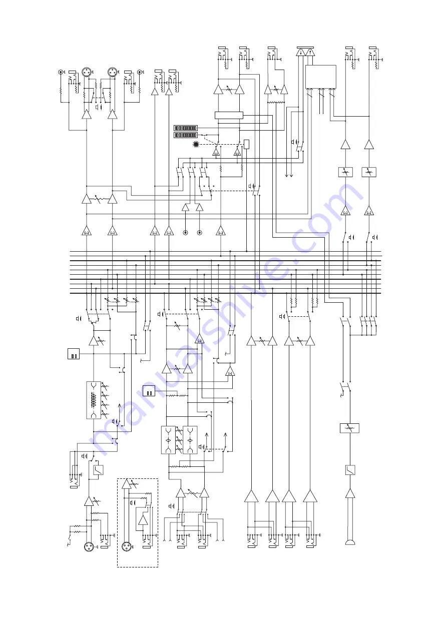
Onyx 1220i
L
R
Aux 1 (post)
Aux 2 (post)
Solo(PFL)
SoloLogic
Main
L/3
R/4
Alt
Aux 1 (pre)
Aux 2 (pre)
L
R
Aux 1 (post)
Aux 2 (post)
Solo(PFL)
SoloLogic
Main
L/3
R/4
Alt
Aux 1 (pre)
Aux 2 (pre)
Solo logi
c
Control Room
leve
l
Main level
Aux Return
2
L
R
Inser
t
HP
F
Solo
Le
ve
l
Pa
n
So
lo
Leve
l
Aux Send
s
Pa
n
Leve
l
Tape
Le
ft
Righ
t
Left/3
Right/
4
Aux 1
Ou
t
Au
x 2 Ou
t
Au
x 1 leve
l
Phones
Contro
l
Room Ou
t
L
R
L su
m
R su
m
Al
t L/3 su
m
Alt R/4 su
m
Aux 1 su
m
Aux 2
su
m
Solo su
m
Leve
l
Aux Return
1
L
R
LO
MI
D
80
10
0~8K
12
K
HI
Aux
1
Tape
Me
te
r
CD/Tape in
L
R
RU
DE
SOLO LE
D
Bal/Unba
l
Bal/Unba
l
Ba
l
Ba
l
Talkback Assign
Alt3/4
CD/Tap
e
Ma
in
C/R Sourc
e
3-Ban
dE
Q
Phones
le
ve
l
Au
x 2 leve
l
Aux
2
to Phones
to Aux1-2
Firewire I/
O
FW
13-1
4
C/
R
di
m
Channel 1-12
dire
ct
out
s
Fire
wire
outputs
Alt 3/
4
Ma
in
L/
R
Al
t 3/
4
Ma
in
L/
R
to Au
x1
to Main L/
R
pos
t
pr
e
pos
t
pr
e
Firewire1-2 to
C/
R
of
f
C/R to
Ma
in
of
f
Lo
w
Cu
t
By
pa
ss
Talkback
NOTE: Switches are shown in the default (out) position.
Mi
c
le
ve
l
+4dB
u
C/R
L
C/
R R
Alt ou
t
Main Ou
t
48
V
Mono
Channels 1-
4
Mic
Lin
e
Gain
+
-
Mic:
0 ~ +6
0d
B
Line
: -2
0 ~ +
40dB
Hi
-Z
Line
Hi-
Z
+
-
Line
Ch 1-2
3-Band EQ
LO
80
2.
5K
12
K
HI
MI
D
LO
80
2.
5K
12
K
HI
MI
D
PK -2
0
PK -2
0
Internal
Talkback mi
c
Leve
l
Stereo
Channels
5-12
L
R
FW
Line
Input from FW 1 re
t
Input from FW 2 re
t
(Ch.
11
-1
2
on
ly
)
(Ch.
11
-1
2
on
ly
)
(Ch.
11
-1
2
on
ly
)
To FW
FW
Ta
p
FW Ta
p
To FW
To FW
-2
0 ~ +2
0d
B
Gain
Mic
75Hz
Po
st
Pr
e
Mod Pt
Mo
d Pt
Mo
d
Pt
Po
st
Pr
e
Mod Pt
Mo
d
Pt
Mo
d
Pt
FW 1-12
FW 15
-1
6
FW 1-2
to
Ch
11-1
2
Phan
to
m
NOTE: Modifications (marked MOD above) must be undertaken by authorized LOUD service centers onl
y
Block Diagram


