background image

26

PPM608

PPM608

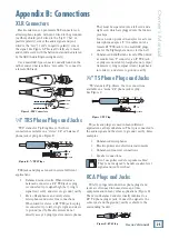
Speakons

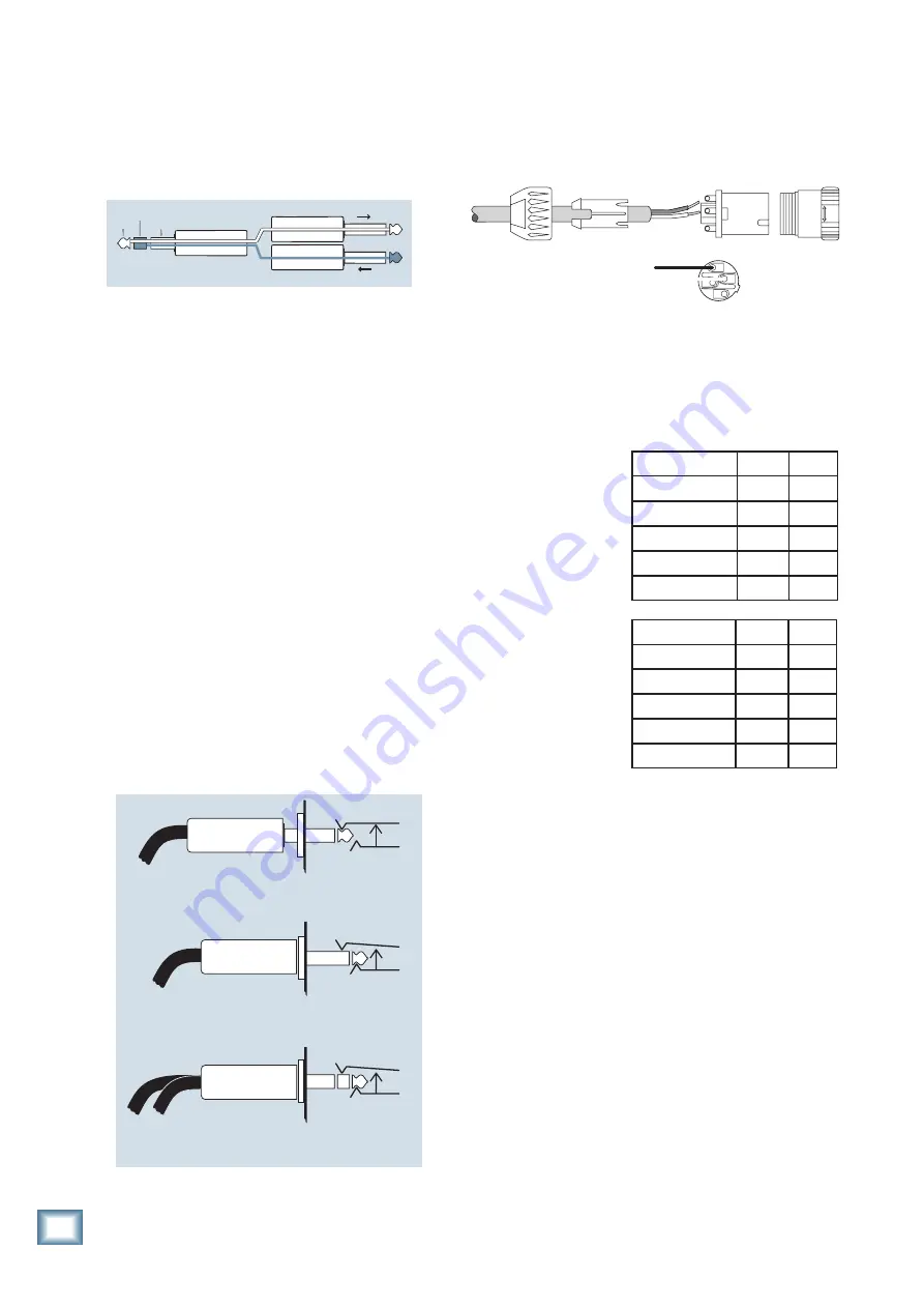
When using the Speakon outputs to connect your 

loudspeakers, wire the Speakon connectors as shown 
below:

Loudspeaker Cable

Use loudspeaker cables with a minimum conductor 

size for the length you need as listed in these tables.

This will minimize 

power losses to less 
than 0.5 dB. The cable 
lengths listed are 
“up to” lengths. For  
in-between lengths, 
use the next larger 
conductor gauge. 
Using larger than the 
recommended  
conductor size is 
always    
permissible. Using 
smaller than  
recommended 
conductor size will 
result in higher power 
losses.

The recommended conductor gauges are listed for 

AWG (American Wire Gauge) and Metric WG (Metric 
Wire Gauge). Note that smaller AWG numbers = larger 
conductors and smaller Metric WG numbers = smaller 
conductors. The Metric WG is equal to ten times the 
nominal conductor diameter in millimeters.

Longer Lengths

For cable lengths over 200 feet / 60 m at 8 ohms, and 

over 100 feet / 30 m at 4 ohms, the conductor sizes  
needed for less than 0.5 dB power losses are rarely 
practical for physical and cost reasons. As a practical 
compromise for these situations the recommended 
conductor gauge is 10 AWG or 25 metric.

TRS Send/Receive Insert Jacks

Mackie’s single-jack inserts are the three- conductor, 

TRS-type 1⁄4" phone. They are unbalanced, but have 
both the mixer output (send) and the mixer input 
 (return) signals in one connector. See Figure E.

The sleeve is the common ground (earth) for both 

signals. The send from the mixer to the  external unit is 
carried on the tip, and the return from the unit to the 
mixer is on the ring.

Using the Send-only on an Insert Jack

If you insert a TS (mono) 1⁄4" plug only  partially (to 

the first click) into a Mackie  insert jack, the plug will 
not activate the jack switch and will not open the insert 
loop in the  circuit (thereby allowing the channel signal 
to continue on its merry way through the mixer).

This allows you to tap out the channel signal without 

interrupting normal operation.

If you push the 1⁄4" TS plug in to the second click, you 

will open the jack switch and create a  direct out, which 
does interrupt the signal in that channel. See Figure F.

NOTE: Do not overload or short-circuit the signal you 

are tapping from the mixer. That will affect the internal 
signal.

“tip”

This plug connects to one of the 

mixer’s Channel Insert jacks.

“ring”

tip

ring

sleeve

SEND to processor

RETURN from processor

(TRS plug)

Figure E

Direct out with no signal interruption to master.

Insert only to first “click.”

Channel Insert jack

Channel Insert jack

Channel Insert jack

Direct out with signal interruption to master.

Insert all the way in to the second “click.”

For use as an effects loop.

(TIP = SEND to effect, RING = RETURN from effect.)

MONO PLUG

MONO PLUG

STEREO 

PLUG

Figure F

Figure G

COLD

HOT

1+

1+

1–

1–

2–

2+

Minimum AWG 4 ohm 8 ohm
  18

10 ft

25 ft

  16

25

50

  14

25

75

  12

50

125

  10

100

200

Min Metric WG 4 ohm 8 ohm
12

3 m

8 m

14

8

15

16

8

25

20

15

40

25

30

60

Summary of Contents for PPM608

Page 1: ...PPM608 OWNER S MANUAL 8 Channel 2 x 500 W Professional Powered Mixer...

Page 2: ...N Changes or modifications to this device not expressly approved by LOUD Technologies Inc could void the user s authority to operate the equipment under FCC rules 20 This apparatus does not exceed the...

Page 3: ...se read the safety instructions on page 2 and this page first Setup The PPM608 powered mixer is designed for ease of operation and to be set up quickly and easily Place the powered mixer in a position...

Page 4: ...th constant Q filters on the main and monitor outputs Tape CD stereo RCA outputs 12 segment stereo output meters on main mix and mono meter on monitor 1 Break switch mutes all mono channels Speakon an...

Page 5: ...2 SEND OUTPUT 14 16 FX FOOTSWITCH 15 17 MON 1 SEND 15 18 MAIN SUB 15 19 MAIN OUTPUTS 15 20 POWER AMP INPUTS 15 CHANNEL CONTROLS 21 MON 1 17 22 FX MON 2 17 23 HIGH EQ 17 24 MID EQ 17 25 LOW EQ 17 26 O...

Page 6: ...z switch pressed in and a keyboard attached to channel 7 s stereo inputs A portable recorder is attached to the stereo tape outputs to record the performance Mackie SRM450v2 powered speakers are conne...

Page 7: ...7 s stereo inputs and a drum machine to channel 8 A Mackie SRM150 powered monitor is connected to the monitor 1 send and acts as a personal stage monitor to the keyboard player The mon 1 knobs of eac...

Page 8: ...eceiver connected to the channel 1 line input a graphic EQ connected to channel 1 s insert jack to help control feedback in the wireless mic a microphone connected to channel 2 and an iPod docking sta...

Page 9: ...tar processor connected to ch 6 insert a keyboard attached to channel 7 s stereo inputs and an electronic drum kit attached to channel 8 Add vocal compression as required by tweaking the compression k...

Page 10: ...a heavy metal guitar solo might not be such a good time As a general guide you should turn on your mixer first before any external power amplifiers or powered speakers and turn it off last This will r...

Page 11: ...channel and a passive stage monitor system on the other Monitor 1 Monitor 2 Channel A is the monitor 1 mix and channel B is the monitor 2 mix In this setup the internal power amplifiers are powering t...

Page 12: ...phantom power is globally controlled by the phantom 42 switch on the front panel The phantom power for all channels is turned on and off together Patchbay section This is where you plug in things suc...

Page 13: ...lug single ended unbalanced micro phones or ribbon mics into the mic input jacks if phantom power is on Do not plug instrument outputs into the mic XLR input jacks with phantom power on unless you kno...

Page 14: ...mix levels are adjusted This is known as pre fader If they want more me and less Keith you can turn up their channel s FX mon 2 control and turn down Keith s If you were using monitor 1 to feed the s...

Page 15: ...er or directly to a powered subwoofer Whatever adjustments you make to the main mix will affect this output below 100 Hz The main mix still plays the full frequency range this sub output is just a mon...

Page 16: ...The stereo channel EQ is a 3 band design just like the mono channel EQ U like Unity gain Mackie mixers have a U symbol on almost every level control It stands for unity gain meaning no change in signa...

Page 17: ...specified frequency For example the low EQ boosts bass frequencies below 80 Hz and continues down to the lowest note you never heard Peaking means that certain frequencies form a hill around the cent...

Page 18: ...d be lost in noise The gain switch allows you to make the initial level adjustment appropriate for the connected device mic or line The channel level controls 27 are more for fine tuning to balance th...

Page 19: ...s off then the input output For example an input signal level of 5 dBu results in an output level of 5 dBu The diagonal line from lower left to upper right represents x y that is input output At the m...

Page 20: ...the amount of boost or cut and it has minimal effect on adjacent bands for all settings of the slider levels There s always some effect on adjacent bands to avoid too much variation or ripple between...

Page 21: ...s are 125 250 500 1k 2k 4k and 8kHz The EQ section comes after the monitor 1 level 39 and just before the monitor 1 meter 41 Therefore as you adjust the EQ keep an eye on the meter in case you over do...

Page 22: ...vely working The LED will pulse in time with how much the limiter is being used in the signal path If the Limiter LEDs come on and stay on for more than a second or two it means the power supply has o...

Page 23: ...X memory after about one second When the powered mixer is turned on the FX section will load up the last used preset 49 PRESET SELECTOR TAP DELAY and LED Rotate this endless control to select one of t...

Page 24: ...oblem stays with the same speaker check the speaker wiring or any speaker fuses Unplug anything from the main line level outputs or other line level outputs such as the sub out FX mon 2 send or mon 1...

Page 25: ...wn adapter for a stereo microphone adapter Y two cables out of a female 1 4 TRS jack to two male XLR plugs one for the Right signal and one for the Left Unbalanced Send Return circuits When wired as s...

Page 26: ...ls in one connector See Figure E The sleeve is the common ground earth for both signals The send from the mixer to the external unit is carried on the tip and the return from the unit to the mixer is...

Page 27: ...ono input 1 4 TRS balanced Line stereo input 1 4 TRS unbalanced Preamp main outputs 1 4 TRS balanced Monitor outputs 1 4 TRS balanced Inserts 1 4 TRS unbalanced Loudspeaker outputs 1 4 TS and Neutrik...

Page 28: ...ycling waste electrical and electronic equipment EEE Improper handling of this type of waste could have a possible negative impact on the environment and human health due to potentially hazardous subs...

Page 29: ...n their default out position Comp Efx Global phantom power phtm phtm Efx 100Hz Low Pass Main Sub Out Efx sum Mon 1 HI Z LINE Hi Z Channel 5 6 only or 1 Meg Mics Mon 2 pre Efx post Mon 1 Mic Gain Mic 2...

Page 30: ...reflections that would be found in a very large stone walled house of worship Gives amazing depth to choirs wind instruments organs and soft acoustic guitars 12 Gated Reverb This preset incorporates...

Page 31: ...ice representative will at its option either repair or replace any such nonconforming product provided that Customer gives notice of the noncompliance within the Warranty Period to the Company at www...

Page 32: ...Road NE Woodinville WA 98072 USA United States and Canada 800 898 3211 Europe Asia Central and South America 425 487 4333 Middle East and Africa 31 20 654 4000 Fax 425 487 4337 www mackie com E mail s...

Reviews: