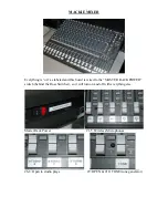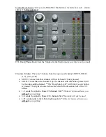
#11-16: L/R Output Channels from the mixer (9) and router monitors (10 &11)
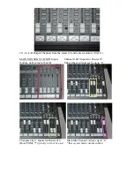
MAIN MIX SUB STATION: Inputs Channels 1&2: Inputs for Router #9
(bottom right corner of board)
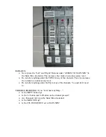
Mixer (these will always be up to ‘0’
Channels 3 & 4: Inputs for Router #14 Main Mix Channel: Always up to ‘0’
(Ross/PGM) **
typically will not be used
*this is your main volume control


