


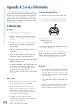
SP260 2x6 Spe
ak
er Pr
oc
es
sor
12
SP260 2x6 Speaker Processor
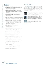
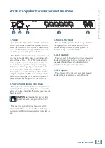
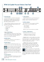
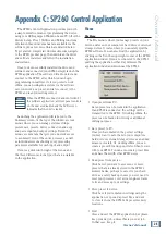
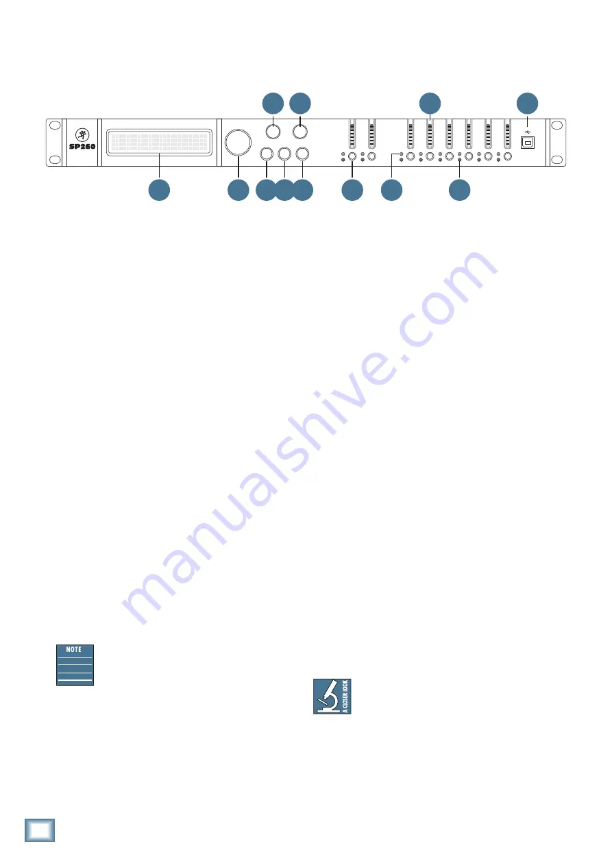
SP260 2x6 Speaker Processor Features: Front Panel
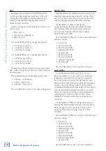
6. LCD Display
The LCD Display is one of the most vital features
of the processor. It displays processor information
including (but not limited to) System, Preset and
Security Utilities, gain, delay, EQ and other input
and output processing parameters.
When the SP260 is powered up, the last state it was
in will load up and the LCD Display will present the
current system setup type:
• 2Sub [default]
• Sub
• 2x3Way
• 3xStereo
• 1x6Way
7. Nav/Edit1 Wheel
The Nav/Edit1 Wheel allows you to navigate the user
interface, edit sections of the processor, navigate within
screens to select sub-menus, pages and parameters,
as well as select values during editing.
8. Edit2 Wheel
The Edit2 Wheel allows you to edit parameters, as
well as select values during editing.
9. Edit3 Wheel
Broken record alert! The Edit3 Wheel allows you to
edit parameters, as well as select values during editing.
Read on to learn more about what each of these
wheels does. In general, use the Nav/Edit1
Wheel to scroll through the various pages and
configuration settings. Depending on the page,
individual parameters may be changed by turning one
(or more) of the wheels. In some cases, the Edit2 and
Edit3 Wheels provide fine and course control of the same
parameter.
10. Enter Button
The Enter Button allows you to dig deeper and deeper
into menus and parameters, confirm operations and
change settings.
NAV/EDIT
1
ENTER
ESC
CLIP
+15
+9
+3
0
-10
-20
LIMIT
CLIP
+15
+9
+3
0
-15
USB
EDIT
MUTE
UTILITY
A
CLIP
+15
+9
+3
0
-10
-20
EDIT
MUTE
B
1
EDIT
MUTE
LIMIT
CLIP
+15
+9
+3
0
-15
2
EDIT
MUTE
LIMIT
CLIP
+15
+9
+3
0
-15
3
EDIT
MUTE
LIMIT
CLIP
+15
+9
+3
0
-15
4
EDIT
MUTE
LIMIT
CLIP
+15
+9
+3
0
-15
5
EDIT
MUTE
LIMIT
CLIP
+15
+9
+3
0
-15
6
EDIT
MUTE
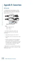
2x6 S P E A K E R
P R O C E S S O R
EDIT
2
EDIT
3
6
17
7 10 11 12
15
14
13
16
11. ESC Button
The ESC Button allows you to retreat from selected
variables. In some cases, it confirm operations and
changes settings, as well. These will be noted.
12. Utility Button
Press this button to select and update the SP260’s
utilities. There are three main utilities menus:
• System Utilities
• Preset Utilities
• Security Utilities
Within each, an array of sub-menus are available.
13. Mute / Edit Buttons
These eight buttons serve a dual purpose:
• Muting selected inputs and outputs
• Editing selected inputs and outputs
To
mute
an input or output, quickly press and release
the desired button once to engage mute; quickly press
and release it again to un-mute. Mute does just what it
sounds like it does. It mutes – turns off – the signal on
the corresponding inputs and outputs.
To
edit
an input or output, press and hold the
desired button until that input or output’s blue
LED [14] illuminates. Press and hold again to take
it out of edit mode. Edit does just what it sounds like
it does. It allows you to edit – change – variables on
the chosen inputs and outputs.
While it is not possible to edit the inputs AND
outputs simultaneously, it is possible to link and
edit the inputs simultaneously OR link and edit
any number of outputs simultaneously. Simply press and
hold any additional input or output Mute / Edit buttons to
link. Any changed parameters will affect all linked inputs
or outputs.
8 9


