


SP260 2x6 Spe
ak
er Pr
oc
es
sor
2
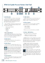
SP260 2x6 Speaker Processor
Important Safety Instructions
Correct Disposal of this product:
This symbol indicates that this product should not be disposed of with your household waste, according to the WEEE Directive
(2002/96/EC) and your national law. This product should be handed over to an authorized collection site for recycling waste electrical and electronic equipment (EEE). Improper handling
of this type of waste could have a possible negative impact on the environment and human health due to potentially hazardous substances that are generally associated with EEE. At the
same time, your cooperation in the correct disposal of this product will contribute to the effective usage of natural resources. For more information about where you can drop off your waste
equipment for recycling, please contact your local city office, waste authority, or your household waste disposal service.
1.
Read these instructions.
2.
Keep these instructions.
3.
Heed all warnings.
4.
Follow all instructions.
5.
Do not use this apparatus near water.
6.
Clean only with a dry cloth.
7.
Do not block any ventilation openings. Install in accordance with the
manufacturer’s instructions.
8.
Do not install near any heat sources such as radiators, heat registers,
stoves, or other apparatus (including amplifiers) that produce heat.
9.
Do not defeat the safety purpose of the polarized or grounding-type
plug.
A polarized plug has two blades with one wider than the other. A
grounding-type plug has two blades and a third grounding prong.
The wide blade or the third prong are provided for your safety. If the
provided plug does not fit into your outlet, consult an electrician for
replacement of the obsolete outlet.
10.
Protect the power cord from being walked on or pinched particularly at
plugs, convenience receptacles, and the point where they exit from the
apparatus.
11.
Only use attachments/accessories specified by the manufacturer.
12.
Use only with a cart, stand, tripod, bracket, or
table specified by the manufacturer, or sold with
the apparatus. When a cart is used, use caution
when moving the cart/apparatus combination to
avoid injury from tip-over.
13.
Unplug this apparatus during lightning storms or
when unused for long periods of time.
14.
Refer all servicing to qualified service personnel. Servicing is required
when the apparatus has been damaged in any way, such as power-
supply cord or plug is damaged, liquid has been spilled or objects have
fallen into the apparatus, the apparatus has been exposed to rain or
moisture, does not operate normally, or has been dropped.
15.
This apparatus shall not be exposed to dripping or splashing, and no
object filled with liquids, such as vases or beer glasses, shall be placed
on the apparatus.
16.
Do not overload wall outlets and extension cords as this can result in a
risk of fire or electric shock.
17.
This apparatus has been designed with Class-I construction and must
be connected to a mains socket outlet with a protective earthing
connection (the third grounding prong).
18.
This apparatus has been equipped with a rocker-style AC mains power
switch. This switch is located on the rear panel and should remain
readily accessible to the user.
19.
The MAINS plug or an appliance coupler is used as the disconnect
device, so the disconnect device shall remain readily operable.
20.
NOTE: This equipment has been tested and found to comply with
the limits for a Class B digital device, pursuant to part 15 of the FCC
Rules. These limits are designed to provide reasonable protection
against harmful interference in a residential installation. This
equipment generates, uses, and can radiate radio frequency energy
and, if not installed and used in accordance with the instructions,
may cause harmful interference to radio communications. However,
there is no guarantee that interference will not occur in a particular
installation.
If this equipment does cause harmful interference to radio or
television reception, which can be determined by turning the
equipment off and on, the user is encouraged to try to correct the
interference by one or more of the following measures:
• Reorient or relocate the receiving antenna.
• Increase the separation between the equipment and the receiver.
• Connect the equipment into an outlet on a circuit different from
that to which the receiver is connected.
• Consult the dealer or an experienced radio/TV technician for help.
CAUTION: Changes or modifications to this device not expressly
approved by LOUD Technologies Inc. could void the user's authority to
operate the equipment under FCC rules.
21.
This apparatus does not exceed the Class A/Class B (whichever is
applicable) limits for radio noise emissions from digital apparatus as
set out in the radio interference regulations of the Canadian Department
of Communications.
ATTENTION
—
Le présent appareil numérique n’émet pas de bruits
radioélectriques dépassant las limites applicables aux appareils
numériques de class A/de class B (selon le cas) prescrites dans le
réglement sur le brouillage radioélectrique édicté par les ministere des
communications du Canada.
22.
Exposure to extremely high noise levels may cause permanent hearing
loss. Individuals vary considerably in susceptibility to noise-induced
hearing loss, but nearly everyone will lose some hearing if exposed to
sufficiently intense noise for a period of time. The U.S. Government’s
Occupational Safety and Health Administration (OSHA) has specified
the permissible noise level exposures shown in the following chart.
According to OSHA, any exposure in excess of these permissible limits
could result in some hearing loss. To ensure against potentially danger-
ous exposure to high sound pressure levels, it is recommended that all
persons exposed to equipment capable of producing high sound pres-
sure levels use hearing protectors while the equipment is in operation.
Ear plugs or protectors in the ear canals or over the ears must be worn
when operating the equipment in order to prevent permanent hearing
loss if exposure is in excess of the limits set forth here:
PORTABLE CART
WARNING
CAUTION
RISK OF ELECTRIC
SHOCK. DO NOT OPEN
CAUTION: TO REDUCE THE RISK OF ELECTRIC SHOCK DO NOT REMOVE COVER (OR BACK)
NO USER-SERVICEABLE PARTS INSIDE. REFER SERVICING TO QUALIFIED PERSONNEL
The lightning flash with arrowhead symbol within an equilateral triangle is
intended to alert the user to the presence of uninsulated "dangerous
voltage" within the product's enclosure, that may be of sufficient magnitude
to constitute a risk of electric shock to persons.
The exclamation point within an equilateral triangle is intended to alert the
user of the presence of important operating and maintenance (servicing)
instructions in the literature accompanying the appliance.
WARNING — To reduce the risk of fire or electric shock, do not
expose this apparatus to rain or moisture.
Duration, per
day in hours
Sound Level dBA,
Slow Response
Typical Example
8
90
Duo in small club
6
92
4
95
Subway Train
3
97
2
100
Very loud classical music
1.5
102
1
105
Fooyoung screaming at desTROYer about deadlines
0.5
110
0.25 or less 115
Loudest parts at a rock concert


