30
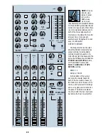
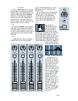
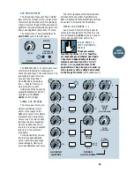
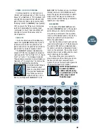
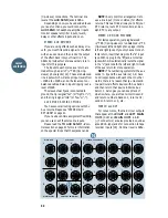
Insert the plug just to
the FIRST click. Do not
push the plug all the way
in. This connection al-
lows you to tap a direct
out without interrupting
the submix bus signal; or
Insert the plug all the way in to the
SECOND click. This also provides a submix
out connection, but the submix signal is
interrupted at that point.
MAIN MIX OUTPUTS
The main SR24•4 outputs appear at sev-
eral places on the rear panel for your mixing
pleasure. Near the middle of the panel you
will find the
LEFT
,
RIGHT
and
MONO
MAIN
outputs. To the left and up a little are
TAPE OUT L
and
R
, and up in the left cor-
ner are
MAIN OUTS L
and
R
.
All of these
outputs are derived from the main left and
right mix buses
.
RIGHT & LEFT MAIN OUT
The stereo
MAIN OUTS
outputs [8]
appear on the two connectors near the center
of the mixer labeled, appropriately enough,
RIGHT
MAIN OUT
and
LEFT MAIN OUT
.
These are male XLR-type connectors, de-
signed to mate with a standard mic cable.
The RIGHT main out and LEFT main out
outputs are electronically balanced, with pin 1
connected to ground, pin 2 to signal “hot” (or
“high” or “+”) and pin 3 to signal “cold” (or
“low” or “–”). With the master fader at unity,
nominal output level is +4dBu.
MONO MAIN OUT
The
MONO MAIN OUT
output [9] is a
sum of the left and right mix buses, buffered
with its own electronically balanced output
amplifiers. Like the right main mix and left
main mix, the
MONO MAIN OUT
appears
on a male XLR-type connector near the center
of the rear panel. Pin 1 is ground, pin 2 is
“hot” (or “high” or “+”) and pin 3 is “cold.”
There is an
OUTPUT LEVEL
control [10]
to trim the level of the
MONO MAIN OUT
signal level. With the master fader at unity,
nominal output level is +4dBu.
MAIN OUTS L & R
The main mix outputs also appear at the
MAIN OUTS L
and
R
1
/
4
" TRS jacks near the
upper left corner of the rear panel [11].
These jacks carry the same signals as the
RIGHT
main mix and
LEFT
main mix
connectors.
MAIN OUTS L
and
R
are impedance
balanced
1
/
4
" TRS (tip-ring-sleeve) phone
jacks with ground wired to sleeve, signal “hot”
(or “high” or “+”) to the tip and signal “cold”
(or “low” or “–”) wired to the ring. You can
connect either balanced or unbalanced inputs
to these outputs. Nominal level is 0dBu.
RIGHT
MAIN OUT
LEFT
MAIN OUT
MONO
MAIN OUT
OUTPUT
LEVEL
PIN 2 = HOT
PIN 3 = COLD
O
O
+6
BALANCED
OUTPUTS
Direct out with no signal interruption to master.
Insert only to first “click”
Channel Insert jack
Channel Insert jack
Direct out with signal interruption to master.
Insert all the way in to the second “click”
MONO PLUG
MONO PLUG
Layout
and Function


