SRM1550 P
o
w
er
ed Sub
w
oof
er
8
SRM1550 Powered Subwoofer
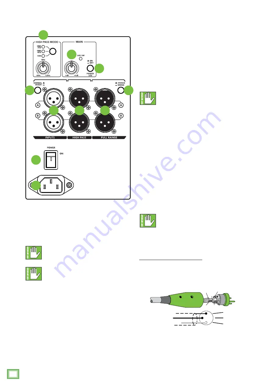
SRM1550 Subwoofer: Rear Panel Features
1. Power Connection
This is a standard 3-prong IEC power connector.
Connect the detachable power cord (included in
the packaging with the subwoofer) to the power
receptacle, and plug the other end of the power
cord into an AC outlet.
Make sure that the AC power is matched to
the AC power indicated on the rear panel
(below the IEC receptacle).
Disconnecting the plug’s ground pin is
dangerous. Don’t do it!
2. Power Switch
Press the top of this rocker switch inwards to turn
on the subwoofer. The front panel LED will glow with
happiness...or at least it will if the subwoofer is plugged
into a suitable live AC mains supply and the power LED
switch [10] is disengaged.
Press the bottom of this rocker switch inwards to turn
off the subwoofer.
As a general guide, the mixer (or other signal
source) should be turned on first, SRM1550
subwoofers next, and loudspeakers last.
As such, the loudspeakers should also be turned off first,
followed by the SRM1550 subwoofers, then the mixer.
This will reduce the possibility of any turn-on or turn-off
thumps and other noises generated by any upstream
equipment from coming out of the speakers.
3. XLR Inputs
Balanced XLR female connectors are provided for the
left and right inputs. Connect the full-range line-level
signal from the mixer (or other signal source) to these
input jacks.
If you are connecting a single subwoofer output, or
LFE (low-frequency effects) output to the subwoofer,
you may use either the A or B input connector.
NEVER connect the output of an amplifier
directly to the input of the subwoofer.
This could damage the input circuitry of the
active subwoofer.
They are wired as follows, according to standards
specified by the AES (Audio Engineering Society):
Balanced XLR Input Connector
Pin 1 – Shield (ground)
Pin 2 – Positive (+ or hot)
Pin 3 – Negative (– or cold)
2
3
1
SHIELD
COLD
HOT
SHIELD
COLD
HOT
3
2
1
Balanced XLR Input Connector
1
2
4
8
3
6
7
10
5
9


