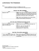
ULTRAMIX SELF TEST PROCEDURE
Setup:
Connect the MIDI OUT jack of the DUT to the MIDI IN jack of the DUT.
Use Control Interface Port test adapter to connect the TX to the RX signal at the CIP
1
.
RAM Test: (Tests SRAM and EEPROM)
RAM Test: (Tests SRAM and EEPROM)
Action:
Response:
Apply power to DUT.
2
PASS:
PASS: The three LEDs on the front panel will light up sequentially
(MIDI first, then Bypass, then Local). All LEDs will then go off and
the Bypass LED will come back on, indicating that the DUT is in its
default power-on mode and is ready for normal operation.
FAIL:
FAIL: The bottom two LEDs (Bypass and Local Mode) will flash
quickly and the DUT will hold in this failure mode.
IO Port Test: (Tests MIDI IO and Control Interface Port IO)
IO Port Test: (Tests MIDI IO and Control Interface Port IO)
Action:
Response:
Simultaneously apply power to DUT and
depress Local Mode switch.
3
PASS:
PASS: All three front panel LEDs should flash at about 4 Hz.
4
FAIL:
FAIL: One (or more) of the LEDs remain unlit.
Bottom (Local Mode) LED = CIP failure
Middle (Bypass) LED = MIDI port failure
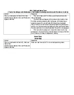
Switch Test: ( Tests the front panel switches )
Switch Test: ( Tests the front panel switches )
Action:
Response:
This is a continuation of the IO Port Test.
Depress each switch, one switch at a time.
When a switch is depressed, its companion LED will go off as long
as the switch is engaged. Release the switch and the LED should
resume flashing.
1
CControl IIntreface PPort
2
If DUT is already powered up, remove power then reapply power.
3
See Note 2
4
The LEDs will not be flashing in sync, but that’s ok.
Summary of Contents for Ultra-34
Page 1: ...ULTRA 34 ULTRAPILOT UNIVERSAL AUTOMATION SYSTEM SERVICE MANUAL 820 178 00 MACKIE DESIGNS INC...
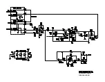
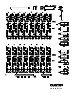
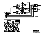
Page 5: ...ULTRAMIX VCA CIRCUIT CHANNEL 1 SHOWN...
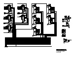
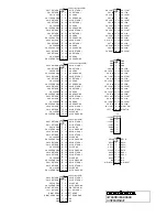
Page 6: ...ULTRAMIX VCA BOARD D A CIRCUIT...
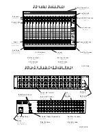
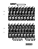
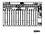
Page 7: ...LEVEL THD LEVEL THD ULTRAMIX VCA BOARD PCB LAYOUT RIGHT HALF...
Page 8: ...ULTRAMIX VCA BOARD PCB LAYOUT LEFT HALF...
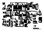
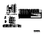
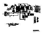
Page 10: ...ULTRAMIX LOGIC BOARD SCHEMATIC...
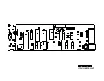
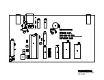
Page 11: ...ULTRAMIX LOGIC PCB LAYOUT...
Page 12: ...ULTRAMIX POWER SUPPLY SCHEMATIC AND PCB LAYOUT...
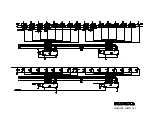
Page 13: ...ULTRAPILOT FADER BOARD SCHEMATIC SHEET 1 OF 2...
Page 14: ...ULTRAPILOT FADER BOARD SCHEMATIC SHEET 2 OF 2...
Page 15: ...ULTRAPILOT FADER BOARD PCB LAYOUT...