Power Amplifier
UP4121
AMPLIFIER
UP4121
oF 6 PAGES
4
O F 4 P A G E S
Architects’ and Engineers’ Specifications
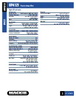
The power amplifier shall have a nominal output power of
at least 120W RMS. It shall operate on 115VAC or 230VAC at
either 50Hz or 60Hz and have its source power supplied by a
detachable IEC power cord. In addition, the unit shall be
capable of being directly powered by a 24Vdc source such as
storage batteries. It shall have a power switch on the front
panel. The unit shall have a constant-impedance output to
drive a 4
Ω
load at its rated output. It shall also have 25V,
50V, 70V and 100V constant-voltage outputs with like per-
formance. The unit shall be capable of being remotely turned
on from a stand-by mode with a contact closure.
The amplifier shall have an active balanced input and an
unbalanced input. The balanced input connection shall be
made through barrier connectors. The unbalanced input shall
have a sensitivity switch on the rear panel to select between
a nominal input signal of 0dB or –20dB. This input shall be
parallel to an unbalanced output connector. Unbalanced con-
nections shall be made through RCA connectors. The unit
shall be capable of being connected to two different input
program sources. The balanced input shall be programmable
to completely exclude the unbalanced input when its priority
link is activated by a contact closure. The inputs shall be
equipped with a high-pass filter and a low-pass filter having
a response of 12dB/octave and fixed 300Hz and 7kHz,
respectively. Each of these filters shall be enabled by a
switch on the rear panel. An overload condition shall cause
an auxiliary voltage of 18Vdc at 300mA to be present at a
pair of terminals on the rear panel.
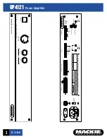
The unit shall have, on its front panel, continuously vari-
able controls for master volume as well as bass and treble
shelving filters. The shelving filters shall have a range of
±12dB with the frequency for the bass fixed at 100Hz and the
treble fixed at 10kHz. LED status indicators shall be provided
on the front panel to indicate power, stand-by mode, signal
present at the output terminals, peak signals near clipping
and an overload condition. The amplifier shall be a model
UP4121 manufactured by Mackie Industrial.
www.mackieindustrial.com
16220 Wood-Red Rd. NE, Woodinville, WA 98072 USA
888.337.7404, fax 425.487.4337, industrial@mackie.com
UK
+44.1268.571.212, fax +44.1268.570.809, info@rcf-uk.com
ITALY
+39.0522.354.111, fax +39.0522.926.208, industrial@rcf.it
FRANCE
+33.3.8546.9160, fax +33.3.8546.9161, rcf.commercial@wanadoo.fr
GERMANY
+49.2572.96042.0, fax +49.2572.96042.10, industrial@mackie.de
Electronic files for this product available at:
www.mackieindustrial.com
This Specification Sheet
UP4121.PDF
Quick-Start Manual
UP4121QS.PDF
Mackie Designs continually engages in research related to product improvement. New material, produc-
tion methods, and design refinements are introduced into existing products without notice as a routine
expression of that philosophy. For this reason, any current Mackie Industrial product may differ in some
respect from its published description, but will always equal or exceed the original design specifications
unless otherwise stated. ©1999-2001 Mackie Designs Inc. All rights Reserved. and are
registered trademarks of Mackie Designs Inc. Mackie Industrial is a trademark of Mackie Designs Inc.
part no. 910-143-10 Rev.B


