background image

7

Owner’s Manual


Hookup Diagrams

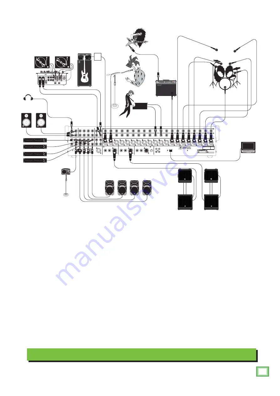
Typical Live Sound System

The drummer is the mic and channel hog of the band; Dustin has the kick, snare and three toms mic'd 

up, in addition to two overhead mics. These run to mic inputs 1-7. desTROYer is rockin' the electric guitar 

through an Ampeg GVT52-212 guitar amp. The amp is mic'd and connected to the channel 8 mic input. 

Keyboard player Chris is connected to the channel 10 and 11 line inputs...well, Chris isn't connected to 

the inputs; his keyboard is! Vocalist Anthony is singing through a mic connected to the mic 19 input. A 

bass guitar is connected to an Ampeg rig which is connected (via DI) to the mic 20 input. The last four 

mono channels of each 24 and 32-channel VLZ4 4•Bus mixer have built-in compressors, so feel free to 

"squeeze" the vocals and bass to heart's desire since they lie here. Last, but not least, a DJ is spinning 

records connected (via a d.2 Pro DJ mixer) to the line inputs on stereo channels 21/22. The sound guy 

(or gal) may monitor levels using headphones (via the headphones output) and/or a pair of MR8mk3's 

connected to the monitor L/R outputs.

Four SRM450v2 powered speakers are used as stage monitors for the band; they are connected to the 

aux 1-4 send jacks. An SRM150 powered speaker receives a mono input from the aux 5 send, and is 

used as a monitor for Chris (the keyboard player). Graphic EQs are connected to aux inserts 1-4 to help 

prevent feedback.

The club is driven by connecting a pair of DLM12S powered subwoofers and a pair of DLM12 


powered speakers to the main left and right outputs. 

A laptop connects to the mixer via the USB port, allowing the 2-channel main mix to be recorded. 


Any music (iTunes

®

, mp3s, or other pre-recorded audio) may be played back from the laptop, as well. 

These can enter as either a source for the monitor and phones, or any available channels.

POWER

ON

PHANTOM

ON

3

2

1

2

1

2

1

6

5

4

3

2

1

6

5

4

3

2

1

4

SUBGROUP OUTS

BAL / UNBAL

SUBGROUP INSERTS

TIP SEND, RINGRETURN

AUX INSERTS 

TIP SEND, RING RETURN

AUX SENDS 

BAL / UNBAL 

3

2

1

4

L

R

MONO

L

R

MONO

STEREO RETURNS 

BAL / UNBAL

21/22

23/24

BAL / UNBAL

BAL / UNBAL

MONITOR

MONO

MONITOR

L

R

100 - 240 V     

50 - 60 Hz  55W

TALKBACK

MIC

RIGHT

MAIN OUT

INSERT

LINE

LEFT

MAIN OUT

INSERT

LINE

MONO

MAIN OUT

INSERT

LINE

LEVEL

OUTPUT

L

USB

R

L

R

TAPE

OUT

IN

TIP SEND

RING RETURN 

TIP SEND

RING RETURN 

TIP SEND

RING RETURN 

BAL / UNBAL

BAL / UNBAL

 BAL / UNBAL

20

20

20

19

19

19

18

18

18

17

17

17

16

16

16

15

15

15

14

14

14

13

13

13

12

12

12

11

11

11

10

10

10

9

9

9

8

8

8

7

7

7

6

6

6

5

5

5

4

4

4

3

3

3

2

2

2

1

1

1

ONYX MIC PREAMPS

LINE

 (BAL / UNBAL)

INSERTS

 (TIP SEND, RING RETURN)

L

INE

 (BAL / UNBAL)

I

NSERTS

 (TIP SEND, RING RETURN)

ONYX MIC PREAMPS

UNBALANCED

REVISION

SERIAL NUMBER

REPLACE WITH THE SAME TYPE FUSE AND RATING.
DISCONNECT SUPPLY CORD BEFORE CHANGING FUSE

UTILISE UN FUSIBLE DE RECHANGE DE MÊME TYPE.
DEBRANCHER AVANT DE REMPLACER LE FUSIBLE

WARNING:

 TO REDUCE THE RISK OF FIRE OR ELECTRIC

SHOCK, DO NOT EXPOSE THIS EQUIPMENT TO RAIN OR
MOISTURE.  DO NOT REMOVE COVER. NO USER SERVICEABLE
PARTS INSIDE. REFER SERVICING TO QUALIFIED PERSONNEL.

AVIS: RISQUE DE CHOC ELECTRIQUE — NE PAS OUVRIR

THIS DEVICE COMPLIES WITH PART 15 OF THE FCC RULES FOR THE U.S. AND THE ICES-003 FOR CANADA.  OPERATION 
IS SUBJECT TO THE FOLLOWING TWO CONDITIONS: (1) THIS DEVICE MAY NOT CAUSE HARMFUL INTERFERENCE, AND  
(2) THIS DEVICE MUST ACCEPT ANY INTERFERENCE RECEIVED, INCLUDING INTERFERENCE THAT MAY CAUSE 
UNDESIRED OPERATION.

+6

U

power

input

reverb

master

gain

treble

middle

bass

volume

channel

1

1

2

gain

treble

middle

bass

volume

2

off

on

standby

TDSK

half

full

1

2

3

4

hi

lo

ultra hi / lo

5

master

standby

standby/

power/

fault

power

treble

frequency

midrange

bass

gain

-15dB

0dB

ks

pb

no

jd

pa

jh

LINE

MIC

R

R

PGM 2

MAIN OUT

MIC

L

L

L

L

L

R

PHONO

CD

SEND

R

BOOTH

FX

GND

LINE

PHONO

RETURN

L(MONO)

R

R

L

R

LIVE

RECORD

PGM 1

LINE

PHONO

GND

PHONO

CD

R

R

L

L

DLM12

Powered 

Speaker

DLM12

Powered 

Speaker

DLM12S

Powered

Subwoofer

DLM12S

Powered

Subwoofer

Laptop 

Computer 

with audio 

production 

software

Headphones

Turntables with phono-level output

d.2 Pro DJ mixer

MR8mk3

Powered Reference 

Monitors L/R

SRM450v2 Powered Speakers 

for Stage Monitors (Aux Sends 1-4)

Chris 

on keys

Francis

on bass

DI

Box

Dustin

on drums

desTROYer

on six-string

Anthony on 

lead vox

Monitor EQ 

(Aux Inserts 1-4)

SRM150

Powered Monitor

for keyboard player

(Aux Send 5)

Summary of Contents for VLZ4

Page 1: ...4 3 3 3 2 2 2 1 1 1 21 21 22 22 23 23 24 24 25 25 26 26 27 27 28 28 ONYX MIC PREAMPS LINE BAL UNBAL INSERTS TIP SEND RING RETURN LINE BAL UNBAL INSERTS TIP SEND RING RETURN ONYX MIC PREAMPS UNBALANCE...

Page 2: ...rence regulations of the Canadian Department of Communications ATTENTION Le pr sent appareil num rique n met pas de bruits radio lectriques d passant las limites applicables aux appareils num riques d...

Page 3: ...equency 19 34 Low EQ 19 35 High Mid EQ Level 19 36 Low Mid EQ Level 19 37 Pan 19 38 Mute 19 39 OL LED 19 40 Sig LED 20 41 Solo 20 42 Assign 20 43 Channel Fader 20 44 FX1 And FX2 20 45 USB Switch 20 2...

Page 4: ...5 6 Convenient stereo return to mains for music playback or return to channel to implement EQ auxes and more PFL AFL solo modes 60mm long wearing log taper faders High resolution 12 segment stereo me...

Page 5: ...upporttofind FAQs manualsandotherusefulinformation Emailusat techmail loudtechinc com Telephone1 800 898 3211tospeakwithoneofoursplendidtechnicalsupportchaps MondaythroughFriday normalbusinesshours Pa...

Page 6: ...x level and monitor level when making connections to the mixer Better yet turn off the power When shutting down turn off any power amplifiers or powered speakers first When powering up turn them on la...

Page 7: ...AL UNBAL 21 22 23 24 BAL UNBAL BAL UNBAL MONITOR MONO MONITOR L R 100 240 V 50 60 Hz 55W TALKBACK MIC RIGHT MAIN OUT INSERT LINE LEFT MAIN OUT INSERT LINE MONO MAIN OUT INSERT LINE LEVEL OUTPUT L USB...

Page 8: ...through a pair of MR8mk3 s and nod their collective heads to the beat POWER ON PHANTOM ON 3 2 1 2 1 2 1 6 5 4 3 2 1 6 5 4 3 2 1 4 SUBGROUP OUTS BAL UNBAL SUBGROUP INSERTS TIP SEND RINGRETURN AUX INSER...

Page 9: ...instance which don t need external power and aren t affected by it anyway Phantom power may be selected by pressing up on the mixer s phantom 21 switch Never plug single ended unbalanced micro phones...

Page 10: ...annel signal can go out of the insert jack to an external device be processed and come back in on the same insert jack To do this requires a standard insert cable that must be wired thusly Tip Send ou...

Page 11: ...nserts These 1 4 TRS jacks are for connecting serial effects such as compressors equalizers de essers or filters The insert point is after the mix amps but before the group send masters 74 and after t...

Page 12: ...e channel level or main level except in AFL mode therefore turn down the phones level first as soloed channels may be loud The phones output follows standard conventions Tip Left channel Ring Right ch...

Page 13: ...is set to L and subgroup 2 is set to R Any adjustments made to the subgroup drum levels during the show only pertain to the live show itself recording levels are not adjusted in the DAW unless they a...

Page 14: ...o the mic input jacks if phantom power is on Do not plug instrument outputs into the mic XLR input jacks with phantom power on unless you know for certain it is safe to do so Be sure the main level 75...

Page 15: ...15 15 U 15 15 U 20 20 U 20 20 U AUXMASTER LR STEREO RETURNS EQ HI 12k 15 15 U 15 15 U LOW 80Hz 15 15 U FREQ MID 200 2k 800 100 8k EQ HI 12k 15 15 U 15 15 U LOW 80Hz 15 15 U FREQ MID 200 2k 800 100 8k...

Page 16: ...Applying low cut removes all those problems so you can add low EQ without blowing your subwoofers 25 Pad 20 dB Switch In most cases the pad switch will be disengaged However microphones and balanced...

Page 17: ...e chance of distortion due to overloading the input signals Dynamic range is the difference in level between the quietest and loudest parts of a song A compressor squeezes the dynamic range resulting...

Page 18: ...ts or cuts all frequencies past the specified frequency For example the low EQ boosts bass frequencies below 80 Hz and continuing down to the lowest note you never heard Peaking means that certain fre...

Page 19: ...5 U 15 15 U 15 15 U 15 15 U AUXMASTER EQ HI 12k 15 15 U 15 15 U LOW 80Hz 15 15 U FREQ MID 200 2k 800 100 8k EQ HI 12k 15 15 U 15 15 U LOW 80Hz 15 15 U FREQ MID 200 2k 800 100 8k EQ HI 12k 15 15 U 15 1...

Page 20: ...37 they are used to determine the destination of the channel s signal With the pan knob at the center detent the left and right sides receive equal signal levels main mix L R group 1 2 and group 3 4...

Page 21: ...four signals may be recorded simultaneously and a stereo mix returned to the mixer for playback The six auxes receive signals from the channels via the channel aux sends 27 29 Auxes 1 4 may also be f...

Page 22: ...phantom power which lets the mixer send low current DC voltage to the mic s electronics through the same wires that carry audio Semi pro condenser mics often have batteries to accomplish the same thi...

Page 23: ...ase forgive its rudeness it is only trying to help and wants to be your friend 60 Solo Mode Engaging a channel s solo switch 41 will cause this dramatic turn of events Any existing source selection is...

Page 24: ...1 to aux 2 and to main knobs 62 fully counter clockwise to avoid double bussing The talkback feature allows the engineer to communicate with the talent either through the phones output 17 or the aux 1...

Page 25: ...1 Wrm 300ms 7 Warm Theater 19 Delay 2 Brt 250ms 8 Bright Stage 20 Delay 2 Wrm 200ms 9 Warm Hall 21 Delay 3 Brt 175ms 10 Concert Hall 22 Delay 3 Wrm 150ms 11 Cathedral 23 Chorus Dly 300ms 12 Gated Reve...

Page 26: ...e is no need to hold down the switch es when using the talkback feature Simply engage the switch es and begin talking But don t forget to disengage the switch when you re done talking to them or they...

Page 27: ...for example make sure that both group faders ride together to maintain the left right balance 75 Main Mix This stereo fader allows you to adjust the levels of the main mix signals sent to the XLR and...

Page 28: ...ise Turn the channel gains down one by one If the sound disappears it s either that channel or whatever is plugged into it so unplug whatever that is If the noise disappears it s from your whatever Po...

Page 29: ...two mic preamps 2 1 SHIELD COLD HOT 3 SHIELD COLD HOT 3 2 1 Balanced XLR Output Connector SLEEVE TIP SLEEVE TIP RING RING TIP SLEEVE RING Balanced 1 4 TRS Connector You can cook up your own adapter fo...

Page 30: ...ll not activate the jack switch and will not open the insert loop in the circuit thereby allowing the channel signal to continue on its merry way through the mixer This allows you to tap out the chann...

Page 31: ...15 dB sweep 100 Hz 8 kHz High 15 dB 12 kHz Low Cut Filter 18 dB octave 3 dB 100 Hz 4 Band Equalization stereo channels Low 15 dB 80 Hz Low Mid 15 dB 400 Hz High Mid 15 dB 2 5 kHz High 15 dB 12 kHz USB...

Page 32: ...ch LED To Aux 2 Aux 6 Aux 3 Aux 4 Aux 5 Aux 6 Aux 1 Aux 2 HPF In bypass MID Phantom Power To All Mics Phantom Power L R Int FX 1 Out L FX 1 Line LO MID MID 80 400 2 5K 12K HI LO MID MID 80 400 2 5K 12...

Page 33: ...ect Aux 1 Level Preset select FX Preset Display 1 2 Solo Logic Solo USB Out FX 1 Bypass Logic In FX 1 Out L Out R R L Tap FX Mute Active L R Tape Out Main level Aux 3 pre post Aux 4 pre post 3 4 Aux 3...

Page 34: ...5 5 U 60 dB OO SOLO 1 2 3 4 LR OL 20 30 20 10 10 40 50 5 5 U 60 dB OO SOLO 1 2 3 4 LR OL 20 30 20 10 10 40 50 5 5 U 60 dB OO SOLO 1 2 3 4 LR OL 20 30 20 10 10 40 50 5 5 U 60 dB OO SOLO 1 2 3 4 LR OL 2...

Page 35: ...15 15 U FREQ MID 200 2k 800 100 8k EQ HI 12k 15 15 U 15 15 U LOW 80Hz 15 15 U FREQ MID 200 2k 800 100 8k EQ HI 12k 15 15 U 15 15 U LOW 80Hz 15 15 U FREQ MID 200 2k 800 100 8k EQ EQ EQ HI 12k 15 15 U...

Page 36: ...4 Bus Dimensions 6 U 6 0 in 153 mm 1 8 in 46 mm 29 4 in 748 mm 19 1 in 486 mm 6 0 in 153 mm WEIGHT 31 0 lb 14 1kg 6 0 in 153 mm 1 8 in 46 mm 38 0 in 964 mm 19 1 in 486 mm 6 0 in 153 mm WEIGHT 39 0 lb...

Page 37: ...tch to the right will select either Groups 3 4 or Aux 5 6 to feed USB output channels 3 4 For example with both USB ouput switches in the default position up true 4 track recording may be accomplished...

Page 38: ...eflections that would be found in a very large stone walled house of worship Gives amazing depth to choirs wind instruments organs and soft acoustic guitars 12 Gated Reverb This preset incorporates an...

Page 39: ...vice representative will at its option either repair or replace any such nonconforming product provided that Customer gives notice of the noncompliance within the Warranty Period to the Company at www...

Page 40: ...16220 Wood Red Road NE Woodinville WA 98072 USA Phone 425 487 4333 Toll free 800 898 3211 Fax 425 487 4337 www 720trees com...

Reviews: