


999562 – Revision A
P a g e
|
12 of 28
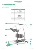
4.5
Slings
Sling Clips should be attached as follows:
1.
Hold the Sling Clip in your hand and attach the clip onto the Safety Belt Clip Pin on the Transfer Aid.
2.
Once the Clip is secure, position the Belt around the lower back of the patient, ensuring the elasticated section is placed
on the user’s lumbar spine and the solid section is place under the user’s coccyx.
Hold onto the other Sling clip with
your hand.
3.
Ensure the Rear Castor brakes are applied.
4.
With the Belt secured on one side of the Transfer Aid, and the other by the caregivers’ hand, the patient may safely lift
themselves onto the Transfer Aid, using the Safety belt as an assistive product only.
5.
Do not use the belt to raise the patient, the patient must be able to lift themselves, with the belt being a support.
6.
While the patient is being lifted, once possible, attach the Safety Belt to the second Clip Pin on the Transfer Aid.
7.
Safety Belt operation complete.
To remove the sling, simply reverse the processes shown in the above statements.
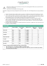
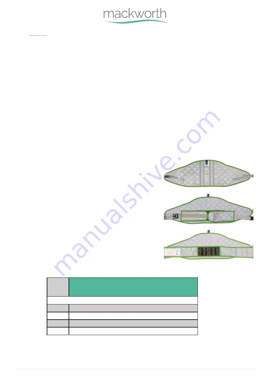
4.5.1
Compatible Belt Types
We recommend the use of the Mackworth manufactured belt range (type ‘B’
applied part) to be utilised with the Mackworth TA400. It is at the user’s
discretion to use alternative supplied product. In utilising another
manufacturer’s belt, checks must first be made to ensure the belt is safe to
use and meets the requirements of BS EN ISO 10535 before its use.
The belts with a safe working load of 180kg (400 lb) that can be used with the
Mackworth TA400 are shown below in Table 3, complete with product codes.
For all components, the lowest maximum safe working load must always be
adhered to.
Size
Mackworth Belt Range - Product Codes
Mackworth TA400 Back Support Belt
Small
1201TAB550C
Medium
1201TAB540C
Large
1201TAB530C
XL
1201TAB520C
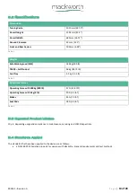
Figure 15
Table 3
Summary of Contents for TA400
Page 1: ...Doc No 999562 Revision of document A Revision Date 24 08 21 TA400 Transfer Aid User Manual...
Page 21: ...999562 Revision A P a g e 21 of 28...
Page 22: ...999562 Revision A P a g e 22 of 28...
Page 23: ...999562 Revision A P a g e 23 of 28...
Page 24: ...999562 Revision A P a g e 24 of 28...
Page 25: ...999562 Revision A P a g e 25 of 28 User notes...
Page 26: ...999562 Revision A P a g e 26 of 28 User notes...
Page 27: ...999562 Revision A P a g e 27 of 28 User notes...


