background image


MS574 0210 0007 

Page 7


2.3. 

OPERATOR INFORMATION AND FUNCTIONS 

 
In general, the ER will always function at Operator level. The information displayed is dependent 
upon the SETUP-settings The signal from the connected sensor is processed by the ER in the 
background, whichever screen refresh rate setting is chosen. After pressing a key, the display will be 
updated very quickly during a 30 second period, after which it will slow-down again. 


Fig. 3: Example of display information during process. 


For the Operator, the following functions are available: 


Display flowrate / total or flowrate 

This is the main display information of the ER. After selecting any other information, it will 
always return to this main display automatically.  
Total is displayed on the upper-line of the display and flowrate on the bottom line. 
It is possible to display flowrate only with the large 17mm digits; in this instance press the 
SELECT-key to read the total.  
When "-------" is shown, then the flowrate value is too high to be displayed. The arrows 


indicate the increase/decrease of the flowrate trend. 


Clear total 

The value for total can be re-initialized. To do so, press CLEAR twice. After pressing CLEAR 
once, the flashing text "PUSH CLEAR" is displayed. To avoid re-initialization at this stage, 
press another key than CLEAR or wait for 20 seconds.  
Re-initialization of total DOES NOT influence the accumulated total. 


Display accumulated total 

When the SELECT-key is pressed, total and accumulated total are displayed. The 
accumulated total cannot be re-initialized. The value will count up to 99,999,999,999. The unit 
and number of decimals are displayed according to the configuration settings for total. 


Low-battery alarm 

When the battery voltage drops, it must be replaced. At first "low-battery" will flash, but as 
soon as it is displayed continuously, the battery MUST be replaced shortly after!  
Only original batteries supplied by the manufacturer may be used, else the guarantee and 
liability will be terminated. The remaining lifetime after the first moment of indication is 
generally several days up to some weeks. 


Fig. 4: Example of low-battery alarm. 


Alarm 01-03 

When "alarm" is displayed, please consult Appendix B: problem solving. 

RUN

LOW BATTERY

RUN

Summary of Contents for ER-M

Page 1: ...FLOWRATE INDICATOR TOTALIZER Electronic Register ER METER MOUNT REMOTE MOUNT ER RMA ER M ER RMP GA012P GB012P Signal input flowmeter NPN and Reed MS574 0210 0007...

Page 2: ...on our products signifies that this product should not be disposed of in general waste or landfill Please contact your local dealer national distributor or Macnaught Technical Services for informatio...

Page 3: ...rocedures which if not performed correctly may lead to personal injury a safety hazard or damage of the ER or connected instruments A caution indicates actions or procedures which if not performed cor...

Page 4: ...8 3 2 2 Overview functions SETUP level 11 3 2 3 Explanation of SETUP functions 12 1 Total 12 2 Flowrate 13 3 Display 14 4 Power management 14 5 Flowmeter 15 6 Others 15 4 Installation 16 4 1 General d...

Page 5: ...Configuration of the unit The ER has been designed to be implemented in many types of applications For that reason a SETUP level is available to configure your ER according to your specific requireme...

Page 6: ...is meant for users operators 2 2 CONTROL PANEL The following keys are available Fig 2 Control Panel Functions of the keys This key is used to program and save new values or settings It is also used to...

Page 7: ...rrows indicate the increase decrease of the flowrate trend Clear total The value for total can be re initialized To do so press CLEAR twice After pressing CLEAR once the flashing text PUSH CLEAR is di...

Page 8: ...are to be observed Ensure that the measuring system is correctly wired up according to the wiring diagrams The housing may only be opened by trained personnel Take careful notice of the Safety rules i...

Page 9: ...rd SETUP at the bottom of the display The number is a combination of two figures The first figure indicates the function group and the second figure the sub function Additionally each function is expr...

Page 10: ...in the other direction When data is altered but ENTER is not pressed then the alteration can still be cancelled by waiting for 20 seconds or by pressing ENTER for three seconds the PROG procedure will...

Page 11: ...our day 23 DECIMALS 0 1 2 3 Ref displayed value 24 K FACTOR 0 000010 9 999 999 25 DECIMALS K FACTOR 0 6 26 CALCULATION per 1 255 pulses 27 CUT OFF 0 1 999 9 seconds 3 DISPLAY 31 FUNCTION total flowrat...

Page 12: ...bic meter The more accurate the K factor the more accurate the functioning of the system will be Example 1 Calculating the K factor Let us assume that the flowmeter generates 2 4813 pulses per liter a...

Page 13: ...UP 21 for example per liter The more accurate the K factor the more accurate the functioning of the system will be For examples read SETUP 13 DECIMALS K FACTOR 25 This setting determines the number of...

Page 14: ...display information influences the power consumption significantly When the application does not require a fast display update it is strongly advised to select a slow refresh rate Please understand t...

Page 15: ...of a serious breakdown or to assess the suitability of your model for upgrade considerations VERSION SOFTWARE 62 For support and maintenance it is important to have information about the characteristi...

Page 16: ...ontact is no longer assured when the housing cover is removed or the panel cabinet has been opened danger from electrical shock The housing may only be opened by trained personnel Take careful notice...

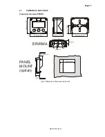
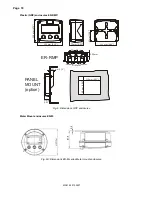
Page 17: ...ENCLOSURE Aluminum enclosures ER RMA 75 mm 2 95 115 mm 4 53 PANEL MOUNT option 29 1 mm 1 15 31 mm 1 22 ER RMA M20 x 1 5 PG9 PG9 30mm 30mm 22 5mm 130 mm 5 12 120 mm 4 72 112 mm 4 40 60 mm 2 36 98 mm 3...

Page 18: ...1 mm 1 15 31 mm 1 22 130 mm 5 12 120 mm 4 72 112 mm 4 40 60 mm 2 36 30mm 30mm D 16mm D 20mm D 16mm 22 5mm 115 mm 4 53 98 mm 3 86 PANEL MOUNT option ER RMP Fig 6 Dimensions GRP enclosures Meter Mount e...

Page 19: ...ate cable glands with effective IP67 NEMA4X seals for all wires Unused cable entries ensure that you fit IP67 NEMA4X plugs to maintain rating A reliable ground connection for both the sensor and if ap...

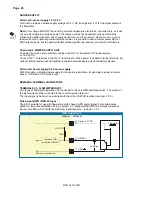
Page 20: ...wer is applied to these terminals the optional internal battery will be disabled enabled automatically to extend the battery life time Terminal 6 Power supply 8 2V sensor supply With this option a lim...

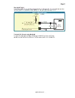
Page 21: ...REED LP low pass filter read par 3 2 3 INTERNAL EXTERNAL Reed switch signal input 2 Common ground unit SIGNAL 1 GND shielding REED SWITCH 3 2V DC 1M low pass filter selection REED LP Flowmeter Termin...

Page 22: ...rnal atmosphere of the ER in such a way that no condensation will occur for example by placing dry silica gel sachet in the casing just before closing it Furthermore it is required to replace or dry t...

Page 23: ...95 LxHxD IP67 NEMA4X Drilling 2x PG9 1x M20 Drilling 2x 16mm 0 63 1x 20mm 0 78 Round meter mount enclosures Classification Type ER M Dimensions 161 x 87 5mm 5 10 x 2 38 xD IP67 NEMA 4X Aluminum meter...

Page 24: ...all pulse signals Operator functions Displayed functions total and or flowrate total and accumulated total total can be reset to zero by pressing the CLEAR key twice Total Digits 7 digits Units L m3...

Page 25: ...ETUP 26 27 The unit has to count the number of pulses according to SETUP 26 within the time according to SETUP 27 Make sure that 27 is set to 10 0 seconds for example the result is that the unit has a...

Page 26: ...13 time unit 13 functional description 5 hardware version 3 installation 16 IP classification 16 keys 6 low battery 7 main function 9 maintenance 22 manual version 3 model 15 operational 6 operator le...

Page 27: ...nel 6 Fig 3 Example of display information during process 7 Fig 4 Example of low battery alarm 7 Fig 5 Dimensions Aluminum enclosures 17 Fig 6 Dimensions GRP enclosures 18 Fig 6A Dimensions ER M serie...

Page 28: ...010 27 cut off time 30 0 sec 3 DISPLAY 31 function total 32 backlight off 33 brightness 5 4 POWER MANAGEMENT 41 LCD new 1 sec 42 mode operational 5 FLOWMETER 51 signal NPN 6 OTHERS 61 model ER ER ER 6...

Reviews: