TROUBLE SHOOTING GUIDE
K6 PUMP UNIT
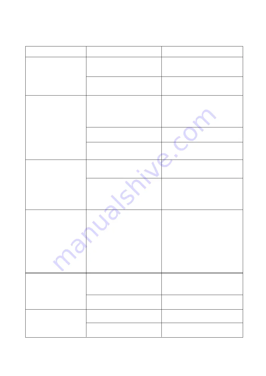
TROUBLE
CAUSE
REMEDY
The pump rod cap rises
slowly when not using the
gun.
( No visible leakages)
The rod cap springs up and
the unit will not pump grease.
The rod cap stays down, but
the unit will not pump grease.
Grease leaks at the top of the
clamp nut (7).
Grease leaks from the bottom
of the strainer cover (11).
Grease leaks from under the
clamp nut (7).
a) Dirt trapped between the inlet ball
(26) and the piston (10).
b) The piston o’ring (25) is defective
or worn.
a) Unscrew the clamp nut (7) and withdraw
the assembly. Clean the ball (26) and
piston (10) thoroughly. Reassemble.
b) Replace the piston o’ring (25).
a) Air lock in the grease caused by :-
i) Dent in the container stopping
the follower
.
ii) Damaged follower o’ring (21).
b) Grease container empty.
c) The footvalve assembly (19) is faulty,
holding the ball (18) off the seat.
a)
i) Remove the dents or tilt the follower
(20) under the dent.
ii) Replace the o’ring (21) in the
follower (20).
b) Change over to a new grease container
or refill the old container with grease.
c) Replace with a new footvalve assembly
(Do not attempt to rework this part).
a) The grade of grease is too Heavy.
b) The strainer (13) is blocked.
a) Use NLGI No2 grease, or lighter.
(Force out the old grease).
b) Unscrew the clamp nut (7) and withdraw
the assembly. Using a screwdriver, lever
off the strainer cover (11).Clean or replace
the strainer (13).
Gland o’ring (6) and back up washer
(5) are defective or worn.
Unscrew the clamp nut (7) and withdraw
the assembly. Hold the piston (10) and
loosen the nut (27), by pushing against the
spring (2) on the clamp nut (7), then carefully
undo the nut (27).
Replace the o’ring (6) and back up washer
(5). When re-assembling, support the
piston (10) when driving the pin (9) home.
Ensure that the flat end of the spring (2) fits
in the cap (1).
a) O’ring (14) damaged.
b) Spot welds broken.
a) Unscrew the clamp nut (7) and withdraw
the assembly. Using a screwdriver, lever
off the strainer cover (11). Replace o’ring
(14)
b) Replace the lid base (15).
a) Dirt under the clamp nut (7).
b) Damaged seal washer (8).
a) Undo and clean surfaces.
b) Replace seal washer (8).
5
Summary of Contents for MINI-LUBE K6
Page 7: ...NOTES 7...


