3) Remove the lid from the grease container. This grease
pump is recommended for use with grease up to and
including NLGI No.2. Heavy grades of grease or cold
temperatures can result in operating difficulties.
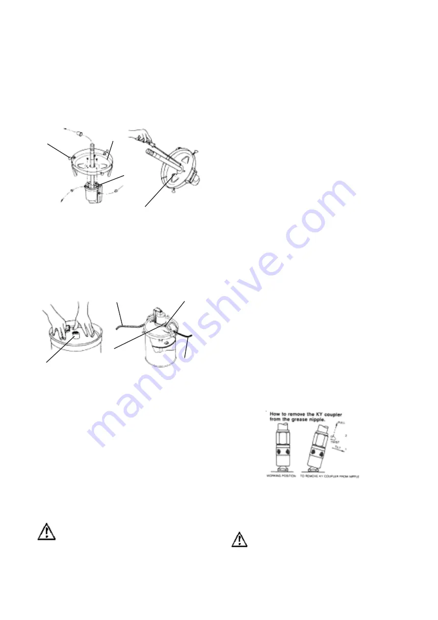
4) Place the follower plate in the grease container with the
follower handle and boss facing upwards (Fig 3). Push
the follower plate down onto the grease until some
grease is forced through the centre (boss) hole.
5) Insert the suction tube through the follower boss and
push the lid / pump assembly down until the lid sits
squarely on top of the grease container. Screw in the lid
positioning the thumb screws equally, until finger tight.
The lid must be centrally located on the grease container.
6) Apply thread tape or other thread sealant to both ends of
the high pressure grease hose. Pass the hose through
the lid assembly and screw the hose into the pump outlet
tightly ( fig 4). Screw the other end of the hose into the
ZSB swivel on the inlet of the B2 booster gun.
7) Before connecting the air supply the customer should
add a “stop” compressed air cock. The air cock must be
a ¼ turn type ( allowing quick closure) and should be
located close to the body of the pump and be easily
recognised. There is a wire mesh strainer located
inside the brass air inlet. It is recommended that a
micro- fine (5 micron) in line air filter be fitted to ensure
maximum efficiency of this pump. Then connect you
airline to the swivel type, brass air inlet.
CAUTION
It is important to read all warnings and operating
instructions before use.
8) Turn on your air supply and press the reset button
(fig 1). Hold the B2 booster gun near a waste container
(to collect the test grease) and squeeze the gun trigger.
The air motor will start to operate and the factory test
grease will appear followed by air (in high pressure
grease hose), followed by your grease. Tighten
connections as required.
(
Fig 1)
(Fig 2)
(Fig 3)
(Fig 4)
Follower Boss
3 Slotted 1/4”
BSW Screws
Thumb Screw
Lid
Reset Button
Remove plugs and
sleeves
Air-Line
Pump outlet
High Pressure
Grease Hose
Seal Condition
Hole (above
pump outlet)
OPERATION
1)
Before connecting the air supply check that all fittings
have been tightly fastened and all hoses are checked
for wear and or damage.
2)
Fully depress the reset button (fig 1), add air cock and
recommended air filter (as described in item ‘2’ of
assembly section) then connect the air supply. The
optimum pressure range is 550 to 700 kPa (80-
100psi / 5.5–7 bar).
3)
When air is connected to the pump and is turned on,
the air motor will start operating, this will allow grease
pressure to build, which pushes grease through the
pump and hose to the grease gun until ‘stall’ pressure
is reached,at this pressure the pump will stop.
For grease delivery press the trigger on the booster
gun. To stop grease delivery release the trigger on the
booster gun. When the trigger is released the grease
flow will stop and the pump will again build to ‘stall’
pressure and stop.
4)
To grease, connect the B2 booster gun coupler to the
grease nipple then squeeze the trigger. Normally, the
air motor will operate and grease will be pumped
through the nipple. If the grease nipple is blocked, the
air motor will stop (stall). If this happens do not
remove the gun from the nipple, just squeeze
the trigger on the B2 gun three or four times. The B2
booster gun has a boost facility which allows the
grease pressure delivered to the grease nipple to be
boosted and will clear most blocked nipples.
Note: The B2 booster gun creates the extra pressure and
not the pump.
5)
Remove the coupler from the grease nipple by first
tilting (to release any pressure) then a twist and pull
motion. Loosen the black coupler cap if difficult to
remove.
CAUTION
Use the lid handles to move the greasing unit. Do not
move the pump by pulling the air or grease hose.
(Fig 5)
2


