background image

                O R D ER   F O R   R EPLA C EM EN T

I T EM PA R T   N o . N o .   o f f

N EW   PA R T / SET

KI T .  R EF D ESC R IPT I O N

B 2 - 1K      ( KI T   A )

59

BJ1

1

PLUNGER GUIDE BUSH

60

BJ23

1

                      BJ1s

A

PLUNGER  

61

BJ3

1

A

BACK-UP WASHER

62

BS008

1

A

O'RING

63

BJ4

1

BJ4s      incl  BJ6, KH5, N403

VALVE BODY

67

KH23

1

KH23

EXTENTION TUBE

68

KY

1

KY

COUPLER ASSEM BLY

69

BJ8

1

BJ8s     incl  BJ20, BJ15, BJ17

GUN BODY

70

N4OO

1

A

1/ 4"  STEEL BALL

71

BJ13

1

                    BJ9s

BALL SUPPORT

72

BJ9

1

A

BALL SPRING

73

BJ19

1

SPRING GUIDE

74

BJ6

1

VALVE INSERT

75

KH5

1

A

VALVE SPRING

76

N403

1

                   BJ24s

A

7/ 32"  STEEL BALL

77

BS013

1

A

O'RING

78

BJ24

1

INLET BODY

79

BJ15

2

TRIGGOR LINK

80

BJ17

2

LINK PIN

81

BJ20

2

                  BJ26s

SCREW

82

N218

1

LOCK NUT

83

N29

1

ADJUSTING SCREW

84

BJ26

1

HIGH NUT

85

BJ25

1

BJ25s

TRIGGER

86

SB6s

2

                   ZSB

SWIVEL ADAPTOR ASSEM BLY

87

SB4s

1

SWIVEL BODY ASSEM BLY

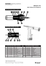
PARTS DIAGRAM

PARTS LIST

59

60

61

62

63 64 65 66 67 68

69

70

71

72

73

74

75

76

77

78

79

80

81

82

83

84

85

86

87

19

6

Summary of Contents for P3 POWERLUBE

Page 1: ...ecause of the high pressures developed by this pump the possibility of fluid injection into the flesh or eyes is a potential hazard Never allow any part of the human body to come in front of or in dir...

Page 2: ...e grease hose followed by your grease Tighten connections as required Fig 1 Fig 2 Fig 3 Fig 4 Follower Boss 3 Slotted 1 4 BSW Screws ThumbScrew Lid Reset Button Removeplugsand sleeves Air Line Pumpout...

Page 3: ...and o ring 12 Note If piston rod is damaged premature wear can occur to piston rod seal 18 11 Remove the strainer tube 53 there are spanner flats on the bottom of this tube 12 Remove the circlip 52 p...

Page 4: ...DIAGRAM 1 2 3 4 5 6 7 8 9 10 11 12 13 3 9 14 15 16 17 18 19 20 21 22 23 24 25 22 15 26 27 28 29 30 31 32 33 34 35 36 3 14 3 4 1 3 37 38 39 40 41 42 43 44 45 46 47 48 49 50 51 52 53 54 55 56 57 38 58...

Page 5: ...der PA30s 31 PA44 1 PA44s incl PA21 VALVE BODY COVER 32 PA15 2 order PA97s END PLUG PIN 33 N37 6 order PA2s incl 6xN37 4xN38 HI LO SCREW 34 PA34 1 PA34s A VALVE SPOOL ASSEM BLY 35 PA95 1 PA97s incl BS...

Page 6: ...O 1 A 1 4 STEEL BALL 71 BJ13 1 BJ9s BALL SUPPORT 72 BJ9 1 A BALL SPRING 73 BJ19 1 SPRING GUIDE 74 BJ6 1 VALVE INSERT 75 KH5 1 A VALVE SPRING 76 N403 1 BJ24s A 7 32 STEEL BALL 77 BS013 1 A O RING 78 BJ...

Page 7: ...ace worn air piston cup seals 10 and or piston 11 a The spool 34 is jammed in the valve body 30 a Lower poppet spring 4 is fatigued b Top poppet spring 4 is fatigued a Use NLGI no 2 or thinner grease...

Page 8: ...roduct such as o rings seals springs and hoses which are subject to wear the warranty period will be 12 months from the date of purchase of the product Macnaught shall at its option repair or replace...

Reviews: