background image

Summary of Contents for VQ2-QUAD

Page 1: ...f C h a r l e s E l e c t r o n i c s L L C 3 0 2S E a s t S t r e e t Mt C a r r o l l I L6 1 0 5 3 C o p y r i g h t 2 0 0 9C h a r l e s E l e c t r o n i c s L L C A l l R i g h t s R e s e r v e d w w w ma c o a n t e n n a s n e t 8 1 5 2 4 4 3 5 0 0 ...

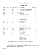
Page 2: ... 13 10 24 SQUARE NUTS ____ S30 4 12 1 SHEET METAL SCREWS ____ S21 12 10 24 MACHINE SCREWS ____ N26 4 10 FLAT WASHERS ____ N12 4 10 LOCK WASHERS ____ F01P 1 COIL FORM ____ PL10 1 1 187 32 PLASTIC CAP BLACK W HOLE ____ Z01P 2 3 GAMMA STRAPS ____ P11 1 BLACK PLASTIC CAP W HOLE ____ 1 TIP SHEET ____ 1 WARRANTY SHEET ____ 1 SET OF INSTRUCTIONS ____ WHEN ORDERING PARTS ALWAYS GIVE PART NUMBER AND DESCRI...

Page 3: ... I G 7 D I R E C T I O N O F R A D I A T I O N B O O M T O M A S T M O U N T I N G S E E F I G 7 FIGURE 1 GENERAL ASSEMBLY INSTRUCTIONS This figure depicts an overall view ofwhat the antenna shouldlook like upon completion of assembly Refer to Figures 2 through 7 for specific assembly details All hardware should be coated with a silicon rubber sealant or similar compound to insure that wind vibrat...

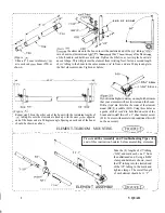
Page 4: ... angle Spacing on each end of the boom 1 should be shown as above I 1 I I 3 64 DRILL I I 1 l 64 D R I L L I I I Ifyouliveinahighwindareayoumayfurtherinsure 1 that your elements will not twist around the boom Drill a 13 64 dia hole thru the center of the element 1 mount BE 1P saddle SO2 Using these holes as I a guide drill a 1 l 64 dia hole thru one side of the boom and install the 12 x 1 sheet met...

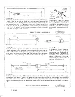
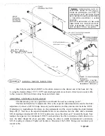
Page 5: ...emaining copper wire start 4 from one end and wrap it around a nail or suitable anchor and twist to form a loop Next string the loose end of the wire thru the hole in the smaller of the two plastic caps PLl 1 Now string the wire thru one of the holes in the coilform FO 1P from inside to out as shown and slid the coilform over the wire to bring its front edge to a distance of 7 l 2 from the loop en...

Page 6: ...own mast I I I I I I I I ADJUSTING STANDING WAVE RATIO I I The dimensions given are approximate and should be used as a starting point I I I I The Gamma Match has 2 adjustments First is the capacitor adjustment and second is the slider I adjustment Connect a S W R bridge between your transmitter and the antenna and check the S W R I I I If adjustment is requiredloosen the clamp on the gammamatch a...

Page 7: ...tal and vertical polarization is achieved through the VQ2 Quad loop configuration Low loss impedance matching GammaMatch assures low S W R for maximum power transfer A pretuned reflector resonating coil assures max F B ratio R E F L E C T O R 7 4 D I R E C T O R D I R E C T I O N The VQ2 Quad s rugged mechanical structure of top grade aluminum tubing 1 I 9 V E R T I C A L assures long lasting depe...

Page 8: ...TER ASSEMBLY INSTRUCTIONS ELEMENT ASSEMBLY n I mgure 3 OPTIONAL 4 n 12 7 l 2 Figure 4A PLll FOI P I I l 6 6 l 12 PLII Figure 5A S O L D E R I OPTIONAL Figure 5C I I I I I I I I I I I I I I I I I I I I I I I I I I I I I I I I I I I I I I I I I I I I I I I I _______________________ ____ _ 7 V QUAD ...

Page 9: ... e m b l y C o n t a c t y o u r l o c a l i n s t a l l e r i f c o n s u l t a t i o n o r a s s i s t a n c e i s r e q u i r e d A l l t o w e r a n d a n t e n n a i n s t a l l a t i o n s s h o u l d b e t h r o u g h l y i n s p e c t e d a t l e a s t t w i c e a y e a r b y q u a l i f i e d e x p e r i e n c e d a n d t r a i n e d p e r s o n n e l t o i n s u r e p r o p e r p e r f o...

Reviews: