I
I
E N D O F B O O M
I
I
I
I
I
(Figure
. .
tubing
.
. . .
- - -
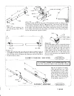
the elements onto the boom, insert the unslotted end of the
(Figure
into a boom-to-element mount
Y).
Now
tnis
I
tne
or tne Doom
a U-bolt, saddle,, and hardware as shown. Tighten the U-bolt so as to crimp the boom into
Slide a 4” boom reinforcer
an oval shape. This will prevent the element from twisting. Next, fasten a second length
,
mto each end
boom (T28) as
of
tubing to the boom in the same manner,
in from, and at a 90 degree angle to
shown.
the first element mount. Tighten as before.
I
(Figure
Repeat step 2B on the other end of the boom with the remaining lengths of
tubing. Be sure the elements are lined up with the ones
opposite
end of the boom and at a 90 degrees angle. Spacing on each end of the boom
should be shown as above.
I
I
D R I L L I
I
- 1
D R I L L
I
Ifyouliveinahighwindareayoumayfurtherinsure
that your elements will not twist around the boom.
Drill a
dia. hole thru the center of the element
mount (BE
saddle (SO2). Using these holes as
a guide, drill a 1
dia. hole thru one side of the
boom and install the
x 1” sheet metal screw
(S3 0). In areas with normal wind conditions this will
not be necessary.
I
I
I
ELEMENT-TO-BOOM MOUNTING
----
- - - - - - - -
---- ----
I
\
Please
read the Assembly and Troubleshooting Tips
at the
end of this instruction booklet before assembling elements.
i
1 1
‘-9”
Take the (4) lengths of
tubing
and mark each one 3” from
I
I
the unflattened end. Using a
clamp and hardware shown, insert
I
the
tubing into the slotted end
of the
tubing to the mark and
tighten clamps. The overall length
I
of each element should be 11’ 9”.
I
I
I
I
I
I
I
I
I
I
ELEMENT ASSEMBLY
- - - - - - - - - - - - - - - - _ _ - _ - - - - - - - - - - - - - - - - - - - - - - - - - - -
3
V QUAD

