Page 16
Reference Manual
Macro-Tech
®
24x6 & 36x12 Power Amplifiers
Note: The components shown in Figure 3.12 are com-
monly available from most electronic supply stores.
Typical fuses help prevent damage due to prolonged
overload, but provide essentially no protection against
damage from large transients. To minimize this prob-
lem, use high-speed instrument fuses such as the
Littlefuse 361000 series. If the loudspeaker is only sus-
ceptible to damage caused by prolonged overload
(such as overheating), use a fuse or circuit breaker hav-
ing the same slow thermal response as the loudspeaker
itself (such as a slow-blow fuse).
3.4 AC Power Requirements
All Macro-Tech
amplifiers are shipped with an appro-
priate line cord. When possible, use a power recep-
tacle on a dedicated circuit and always make sure that
it can supply the correct voltage and current. We do not
recommend operating your amplifier on voltages
greater than 10% above or below the unit’s rated volt-
age. For example, if your amplifier is rated for 120 VAC,
the line voltage should not exceed 132 VAC. See Sec-
tion 7 for power requirements under a variety of condi-
tions.
All specifications in this manual were measured using
120 VAC, 60 Hz power, unless otherwise noted. Speci-
fications were derived using a voltage that is accurate
to within 0.5% with THD less than 1.0% under all testing
conditions. Performance variations can occur at other
AC voltages and frequencies. In addition, line regula-
tion problems directly affect the output power from the
amplifier.
1.0
1.2
1.4
1.6
2.5
3
4
5
6
7
8
9
10
12
14
16
20
25
30
20
15
10
8
6
5
4
3
2
1.5
1
.8
.6
.5
.4
.3
.2
.15
.1
.08
3000
2000
1500
1000
800
600
400
300
200
150
100
80
60
40
30
20
15
10
8
6
4
3
2
1.5
1
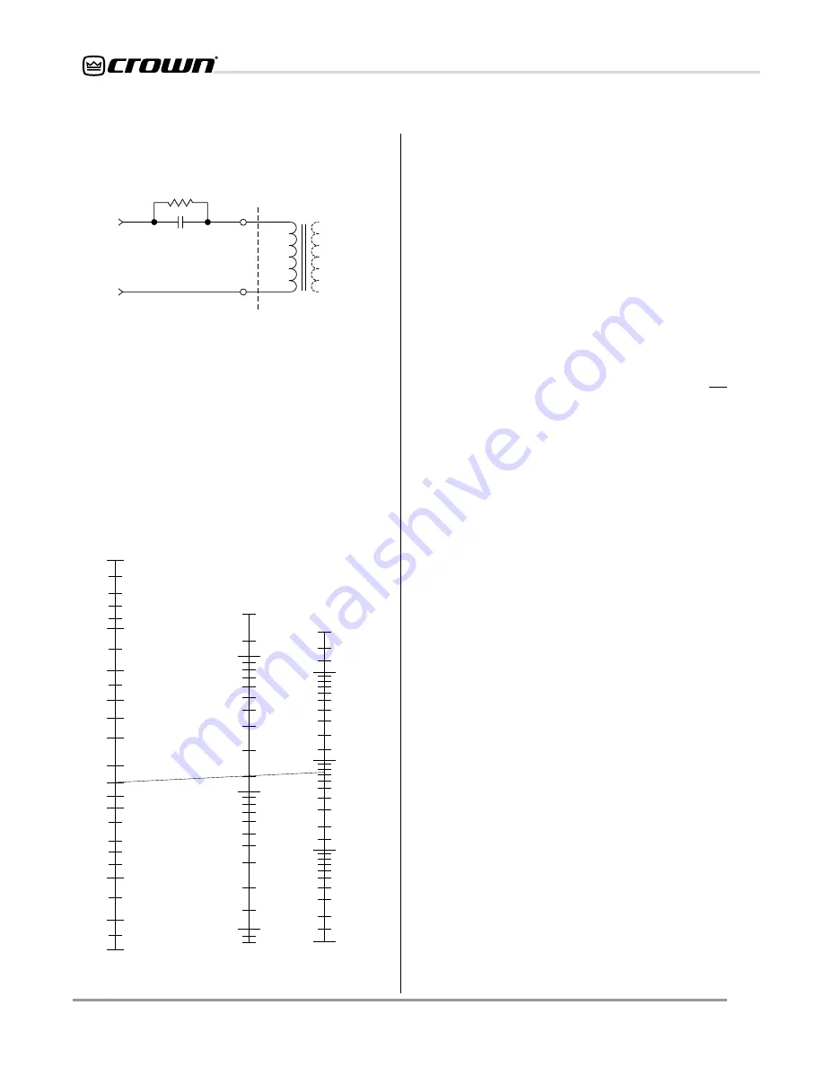
LOUDSPEAKER IMPEDANCE
(ohms)
FUSE
(amps)
LOUDSPEAKER RATING
PEAK MUSIC POWER
(watts)
(Typically 4 times the continuous average power)
Answer: Fuse = 1.5 A
2
40
Example:
Impedance = 8 ohms.
Peak Power = 75 W
Fig. 3.13 Loudspeaker Fuse Selector Nomograph
3.3.3 Additional Load Protection
Because the amplifier generates enormous power, it
may be desirable to protect loudspeakers (or other sen-
sitive loads) from damage due to excessive power. A
common way to do this is to put a fuse in series with the
load. This may be accomplished by using a single fuse
to protect all drivers connected to an output, or each
driver may be fused individually. The nomograph in Fig-
ure 3.13 shows fuse size versus loudspeaker peak
power rating. It can be used to determine what size fuse
to use.
4-ohm, 20-watt
Resistor
590 to 708
µ
f Capacitor
120 VAC, N.P.
+
–
Inductive
Load
+
–
From
Amplifier
Output
Fig. 3.12 Inductive Load (Transformer) Network


