background image

Macro-Tech 3600VZ  Power Amplifier

Page 11

Reference Manual

3 Installation

3.1 Mounting

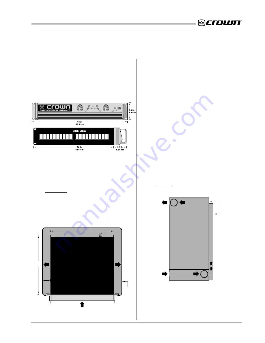
Macro-Tech amplifiers are designed for standard 19
inch (48.3 cm) rack mounting and “stack” mounting
without a cabinet. In a rack cabinet, it is best to mount
them one on top of the other. This provides efficient air
flow and enables each unit to support the one above.

Important:

 Due to its weight, the back of the amplifier

should be supported.

Fig. 3.2  Top View of a Rack-Mounted Unit

If the air supply is unusually dusty, it may be necessary
pre-filter it using commercial furnace filters, etc., to pre-
vent rapid loading of the unit’s own air filter. When
needed, the unit’s filter can be cleaned with mild dish
detergent and water (see Section 4.5).

When mounting the amplifier in a rack cabinet, the side
walls of the rack should be at least 2 inches (5 cm) away
from the chassis as shown in Figure 3.2.

Tip:

 An easy way to verify adequate cooling is to ob-

serve the ODEP indicators with the amplifier operating
under worst-case conditions. If the indicators dim, ad-
ditional cooling is recommended.

If your rack cabinet has a front door that could block air
flow to the amplifier’s air intakes, you must provide ad-
equate air flow either with a grille in the door or by pres-
surizing the air behind the door. Wire grilles are
recommended over perforated panels because they
have larger openings and cause less restriction.

A good choice for increased air flow behind a rack cabi-
net door is to mount one or more “squirrel cage” blow-
ers in the rack (Option 1 below). The blower is mounted
at the bottom of the rack so it blows outside air into the
space between the door and the front of the amplifiers.
This blower should not blow air into or take air out of the
space behind the amplifiers. For racks without a door,
mount a blower at the top of the rack so air is drawn out
the back (Option 2 below). The blower must provide air
flow that exceeds the sum of the air flow required by the
individual amplifiers.

Fig. 3.3  Proper Air Flow in a Rack Cabinet

Fig. 3.1  Mounting Dimensions

3.2 Cooling

NEVER block the amplifier’s side vents and front air in-
take. Under demanding conditions, there should be a
minimum air flow of 45 cubic feet (1.3 cubic meters) per
minute per amplifier. When mounted in a rack, all empty
spaces should be covered with blank panels to prevent
improper air flow. The amplifier’s air flow should be aug-
mented with a rack cooling system if its load is less than
4 ohms and it must operate at consistently high output
levels as in concert sound reinforcement.

AIR

FLOW

AIR FLOW

AMPLIFIER

(TOP VIEW)

RACK

CABINET

16 in

40.6 cm

2 in

(5 cm)

MIN.

IMPORTANT: Be sure rear of amplifier

is securely mounted to rack.

17 in

43.2 cm

AIR

FLOW

BLOWER

(OPTION 2)

BLOWER

(OPTION 1)

AIR

FLOW

FRONT

OF

RACK

DOOR

AIR

FLOW

EQUIPMENT

RACK

(SIDE VIEW)

Summary of Contents for 3600VZ

Page 1: ...tional Inc Other trademarks are the property of their respective owners Obtaining Other Language Versions To obtain information in another language about the use of this product please contact your lo...

Page 2: ...riodofthree 3 yearsfromthedateofpurchasebytheoriginalpurchaser the warrantyperiod thatthenewCrownproductisfreeofdefectsinmaterials and workmanship We further warrant the new Crown product regardless o...

Page 3: ...enance instructions WARNING TO REDUCE THE RISK OF ELECTRIC SHOCK DO NOT EXPOSE THIS EQUIPMENT TO RAIN OR MOISTURE Magnetic Field CAUTION Do not locate sensitive high gain equipment such as preamplifie...

Page 4: ...lectrician for replacement of the obsolete outlet 10 Protect the power cord from being walked on or pinched particularly at plugs convenience recep tacles and the point where they exit from the appara...

Page 5: ...ircuits 21 4 3 1 Output Device Emulation Protection ODEP 21 4 3 2 Standby Mode 22 4 3 3 Transformer Thermal Protection 22 4 3 4 Circuit Breaker 22 4 4 Controls 23 4 5 Filter Cleaning 24 5 Technical In...

Page 6: ...graph 17 3 14 Inductive Load Transformer Network 18 3 15 Loudspeaker Fuse Nomograph 19 4 1 Indicators 20 4 2 Macro Tech Indicator States 21 4 3 Input Sensitivity and Ground Lift Switches 23 5 1 A Typi...

Page 7: ...your new amplifier We strongly recommend you read all instructions warnings and cautions contained within Be sure to read Sections 3 3 2 and 3 3 3 if you plan to use the amplifier in one of its two m...

Page 8: ...n the in dustry High damping factor provides superior control over low frequency drivers for a clean accurate low end An articulated VZ power supply for each channel provides excellent crosstalk chara...

Page 9: ...nel 2 IOC indicator will stay on in Parallel Mono mode refer to Section 4 2 D ODEP Indicators During normal operation of the Output Device Emula tion Protection circuitry these indicators glow brightl...

Page 10: ...el with the PIP connector they should not be used as inputs if the installed PIP has active circuitry Caution The Channel 2 input should NOT be used in either mono mode L Ground Lift Switch The input...

Page 11: ...commended over perforated panels because they have larger openings and cause less restriction A good choice for increased air flow behind a rack cabi net door is to mount one or more squirrel cage blo...

Page 12: ...on the rear panel There are VERY IMPORTANT wiring differences be tween these three modes which are discussed next 3 3 1 Stereo Two Channel Operation The installation is very intuitive in Stereo mode T...

Page 13: ...CHANNEL 2 IN PUT or the signal level and quality may be greatly de graded Keep the Level control of Channel 2 turned completely down counterclockwise Note The input jack and level control for Channel...

Page 14: ...u face the back Connect the input signal to Channel 1 only DO NOT USE THE CHANNEL 2 INPUT or the sig nal level and quality may degrade greatly Turn off the Channel 2 Level control full counterclockwis...

Page 15: ...ing Fig 3 9 Balanced and Unbalanced Phone Plugs positive the ring is negative and the sleeve is ground see Figure 3 9 Wiring for various sources fol lows the XLR wiring guidelines shown in Figures 3 7...

Page 16: ...has plenty of room on its circuit board for input filters A third problem to avoid is hum The two most common sources of hum in an audio system are inductive cou pling and ground loops Inductive coup...

Page 17: ...ograph in Figure 3 13 and the procedure that follows to find the recommended wire gauge AWG or American Wire Gauge for your system Fig 3 13 Wire Size Nomograph Use Good Connectors 1 To prevent possibl...

Page 18: ...factors are 50 or lower Higher damping factors yield lower distortion and greater motion control over the loud speakers A common damping factor for commercial ap plications is between 50 and 100 High...

Page 19: ...the Littlefuse 361000 series If the loudspeaker is only susceptible to damage caused by prolonged overload such as over heating use a fuse or circuit breaker having the same slow thermal response as...

Page 20: ...ower supply is working It does not indi cate the high voltage supply status As a result disrup tion of the high voltage supplies has no effect on the Enable indicator This means that in the improbable...

Page 21: ...stics capabilities Protection systems include ODEP standby and an AC circuit breaker These fea tures provide protection under any conditions 4 3 1 Output Device Emulation Protection ODEP Crown invente...

Page 22: ...cessively clipped input signals can activate this system The amplifier s fault protection system will put an ampli fier channel into standby mode in rare situations where heavy common mode current is...

Page 23: ...dge Mono or Parallel Mono mode turn down the Channel 2 Level control and only use the Channel 1 control The Input Sensitivity Switch is located inside the back of the amplifier Figure 4 3 It is set at...

Page 24: ...ust filters are provided on the air intakes to the cooling system Figure 2 1 If these filters become clogged the unit will not cool as efficiently as it should and may produce lower than normal output...

Page 25: ...as two composite NPN and two composite PNP devices The devices connected to the load are referred to as high side NPN and PNP and the devices connected to ground are referred to as low side NPN and PN...

Page 26: ...switch embedded in each transformer protects them from overheating The low voltage transformer TF 1 uses a separate fan motor winding The TF 1 output is rectified by diodes D1 4 delivering an unregula...

Page 27: ...Macro Tech 3600VZ Power Amplifier Page 27 Reference Manual Fig 5 5 Circuit Block Diagram...

Page 28: ...hen current at any one instant exceeds the design criteria the limiters remove the drive from the LVAs thus limiting current in the output stage to a safe level To further protect the output stages a...

Page 29: ...ts into 8 ohms Bridge Mono mode 3505 watts into 4 ohms 3140 watts into 8 ohms Parallel Mono mode 3555 watts into 1 ohm 3190 watts into 2 ohms 100 VAC International Units Stereo mode with both channels...

Page 30: ...nnector Balanced inch phone jacks on chassis and internal PIP connector Balanced 3 pin XLR connectors are provided on the P I P FX which is a standard feature Input Impedance Nominally 20 k ohms balan...

Page 31: ...height 16 inch 40 6 cm depth behind mounting surface and 2 5 inches 6 4 cm in front of mounting surface Approximate Weight Center of gravity is 6 inches 15 2 cm behind the front mounting surface 120...

Page 32: ...turers qualify their specs by saying they are typical subject to manufacturing tolerances single channel driven or that they are specified with fuses Figure 6 1 Minimum Power Matrix bypassed Each of t...

Page 33: ...Operating the amplifier at levels higher than 0 05 THD can result in output power levels that are higher than those listed in the maximum power matrices Maximum Power Notes All maximum power specifica...

Page 34: ...g 6 4 Typical Damping Factor Fig 6 5 Typical Output Impedance 10 100 1 K 10 K 100 K FREQUENCY Hz 2 1 0 1 2 3 4 dB 5 6 7 4 ohm 8 ohm 1 watt 504 0 126 8 31 8 MILLIOHMS 8 0 2 0 6 dB 20 100 1 K 10 K 20 K...

Page 35: ...mplifier Page 35 Reference Manual Fig 6 7 Typical Crosstalk Fig 6 6 Typical Phase Response TEF 45 0 45 100 1 K 10 K 20 K FREQUENCY Hz 100 1 K 10 K 20 K FREQUENCY Hz dB TEF 60 66 72 78 84 96 90 TEF Mea...

Page 36: ...956 1 538 1 119 701 19 7 16 0 12 2 8 5 4 8 27 1 21 9 16 7 11 5 6 3 31 0 25 0 19 0 13 0 7 1 Duty Cycle AC Mains Power Draw Watts btu hr Current Draw Amps 8 9 7 3 5 6 3 9 2 2 12 3 9 9 7 6 5 2 2 9 14 1...

Page 37: ...each amplifier can be monitored and individually controlled from an inex pensivePC Atotalof15functionscanbeeithermonitored orcontrolled Memorybackupisalsoincorporatedincase ofpowerfailure RequiresanI...

Page 38: ...h pass filter foreachchannel Fastorslowattachandreleasetimescan be set independently for each channel P I P FXT uses balanced 1 1 transformers to isolate the source from the inputs It comes with balan...

Page 39: ...can be used to se cure your amplifier s level controls in situations where the front panel controls are subject to tampering One is needed for each channel They can be ordered through the Crown Servic...

Page 40: ...of purchase and the defective unit to the Crown factory For warranty service we will pay for ground shipping both ways in the United States Contact Crown Factory Service or Technical Support to obtai...

Page 41: ...________________________________ ______________________________________________________________________________ ______________________________________________________________________________ _________...

Reviews: