background image

© 2014 MacroAir Technologies          Toll Free: 866 668 3247          Fax: 909 890 2313          www.macroairfans.com          5

Rev. Date 111714      

Fan Clearance & Placement

WARNING: FANS ARE NOT MEANT TO BE OPERATED IN WINDY CONDITIONS.

Maximum Angle for Mount (feet)

Slope (in)

0

2/12

4/12

6/12

8/12

10/12

Roof Angle

0

9.5

o

18.4

o

26.6

o

33.7

o

39.8

o

Diameter

Recommended Total Drop (Mount to Blade) Length

6 feet

2

2

2

N/A*

N/A*

N/A*

8 feet

2

2

2

N/A*

N/A*

N/A*

10 feet

2

2

2

N/A*

N/A*

N/A*

12 feet

2

2

3

N/A*

N/A*

N/A*

*The Rapid Mount Commercial does not support this angle

The extension lengths above are minimum recommendations only, based solely on roof pitch 

and fan diameter. Other factors must be evaluated when determining extension requirements. 

In addition, OSHA requirements state that the fan airfoils must be a minimum of 10 feet (3.05 

meters) above the floor. Contact our technical department for assistance with fan placement and 

extension selection (technical support contact information can be found on page


29). 

Minimum Clearance (Horizontal / Vertical inches):

Airfoil / Extension

1

2

3

4

5

6

7

8

9

10

6 feet

3 / 3

3 / 3

3 / 3

3 / 3

3 / 3

3 / 3

3 / 3

3 / 3

3 / 3

3 / 3

8 feet

3 / 3

3 / 3

3 / 3

3 / 3

3 / 3

3 / 3

3 / 3

3 / 3

3 / 3

3 / 4

10 feet

3 / 3

3 / 3

3 / 4

3 / 4

3 / 4

3 / 4

3 / 4

3 / 4

3 / 4

3 / 4

12 feet

3 / 4 

3 / 4

3 / 4

3 / 4

3 / 4

3 / 4

3 / 5

3 / 5

3 / 5

3 / 5

The table above shows the clearance needed from the fan to obstructions such as lighting, 

conduit, etc.

Summary of Contents for 370 Airvolution D

Page 1: ...2014 MacroAir Technologies Toll Free 866 668 3247 Fax 909 890 2313 www macroairfans com 1 Rev Date 111714...

Page 2: ......

Page 3: ...Beam Mounting 11 1 3 Glulam Wood Beam Mounting 13 Step 2 Extension and Motor Unit Installation 15 2 1 Extension and Motor Unit Installation 16 Step 3 Safety Cable and Electrical Installation 17 3 1 To...

Page 4: ...nts are available Follow the included wiring schematics and installation instructions when installing this device to ensure proper operation Do not make any changes to any part of the fan without firs...

Page 5: ...ge crosshatched circle to alert personnel of the overhead location of fans Weight Considerations We recommend that a building structure be capable of holding approximately twice the stated hanging wei...

Page 6: ...ll our Technical Department for guidance Technical Support contact information can be found on page 29 However it is your sole responsibility to see that the installation is completed to code and that...

Page 7: ...s only based solely on roof pitch and fan diameter Other factors must be evaluated when determining extension requirements In addition OSHA requirements state that the fan airfoils must be a minimum o...

Page 8: ...DO NOT SCALE DRAWING 9 9 2014 7 17 201 7 17 201 xxxx xxxx xxxx xxxx MD JH EV UNLESS OTHERWISE SPECIFIED NAME DATE COMMENTS Q A MFG APPR ENG APPR CHECKED DRAWN FINISH MATERIAL INTERPRET GEOMETRIC TOLE...

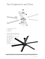
Page 9: ...ents and Tools A 0 442 1 5 C B D A D Drive Motor Controller B Bottom Cover C XS Airfoil D Top Cover Tools Required for Provided Hardware 5 32 Allen Wrench 1 8 Allen Wrench Mount Set Screw 3 32 Allen W...

Page 10: ...croAir Technologies Toll Free 866 668 3247 Fax 909 890 2313 www macroairfans com 8 Rev Date 111714 Step 1 Fan Mounting Choose the appropriate method for mounting the fan s based upon your specific app...

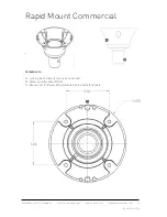
Page 11: ...866 668 3247 Fax 909 890 2313 www macroairfans com 9 Rev Date 111714 Rapid Mount Commercial A C Components A Locking Set Screws 2 locations on mount B Extension Attachment Point C Break outs for Power...

Page 12: ...ng www unistrut us If the spanning distance is greater than 6 feet P1000 or 10 feet P1001B please consult a Structural Engineer Please refer to pg 3 for a list of fan weights and torques 1 1 1 Cut two...

Page 13: ...o the building structure can vary greatly and we recommend Unistrut be contacted so they may recommend the best method to attach the Unistrut to the building www unistrut us Please refer to pg 3 for a...

Page 14: ...cial G I Beam H Extension Attachment Point 1 2 3 Once the Unistrut is attached to the mount you can use the recommended hardware to attach the assembly to your I Beam or Bar Joists 1 2 4 Ensure that t...

Page 15: ...m and position the holes so that they are the furthest from the edge as possible Keep in mind there are breakouts for wire and safety cable around the upper edge of the Rapid Mount Commercial Determin...

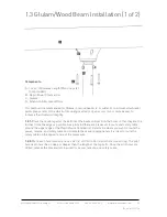
Page 16: ...ap between the top of the mount and the bottom of the beam to run wire and cable 1 3 4 Once the power wire remote cable and safety cable have been routed and are sitting in their appropriate breakouts...

Page 17: ...logies Toll Free 866 668 3247 Fax 909 890 2313 www macroairfans com 15 Rev Date 111714 Step 2 Extension Motor Unit Installation Attach the extension to the bottom of the mount and the motor to the bot...

Page 18: ...ts 2 D Rapid Mount Commercial E Extension F Motor Unit 2 1 1 The image above illustrates the proper assembly of the motor unit extension and mount The provided hardware can be installed and hand tight...

Page 19: ...es Toll Free 866 668 3247 Fax 909 890 2313 www macroairfans com 17 Rev Date 111714 Step 3 Safety Cable and Electrical Installation Install the Safety cable and insert the wires into the appropriate te...

Page 20: ...ded wall anchors and screws 3 1 2A Snap the front of the enclosure to the base plate 3 1 3A Plug in the pre wired CAT5e cable from the screen into the RJ45 coupler inside the enclosure 3 1 4A Secure t...

Page 21: ...2014 MacroAir Technologies Toll Free 866 668 3247 Fax 909 890 2313 www macroairfans com 19 Rev Date 111714 3 1 Touchpad Remote Drawings Remote Enclosure Remote LCD Display...

Page 22: ...o no slack in the safety cable Avoid sharp edges 3 2 2B For I beam installation beam clamps can be used with eye bolts Attach the beam clamps on both sides of the beam and route the safety cable throu...

Page 23: ...chnologies Toll Free 866 668 3247 Fax 909 890 2313 www macroairfans com 21 Rev Date 111714 Step 4 Airfoil Installation Remove the bottom cover install the airfoils to the airfoil clamps and re attach...

Page 24: ...Date 111714 Components A 8 32 x 1 1 4 Bolts B Bottom Cover C Airfoil Clamps D Remote Cable E Power Wires 3 1 1 Remove the three allen bolts that secure the bottom cover and remove the bottom cover to...

Page 25: ...nd tighten until snug Repeat the last step until all three airfoil bolts are installed snugly If the bolts seem like they will not tighten chances are they are not seated in the airfoil clamp properly...

Page 26: ...247 Fax 909 890 2313 www macroairfans com 24 Rev Date 111714 Components A 8 32 x 1 1 4 Bolts B Bottom Cover 4 1 4 Re install the bottom cover using the provided allen bolts and torque bolts snugly Fin...

Page 27: ...ree 866 668 3247 Fax 909 890 2313 www macroairfans com 25 Rev Date 111714 Step 5 Touchpad Remote Navigation and Operation Choose one of the two methods to mount the touchpad remote and configure the f...

Page 28: ...rd Reverse Alternate between forward and reverse operation B Power Button Turn the screen off C Speed Up Speed Down Increase or decrease the speed of the fan D Speed Box Real time indication of fan sp...

Page 29: ...reen you must touch the upper right corner of the home screen reference hidden button on page 26 to get back to the fan diameter selection screen 5 2 2 Once on the home screen test your fan by setting...

Page 30: ...wners keep airfoils clean by having a maintenance person or skilled trade professional who has experience using a lift wipe the fan airfoils with a rag or sponge using hot water or regular cleaning so...

Page 31: ...need to pay shipping removal and installation costs if your AirVolution D needs to be repaired or replaced due to a manufacturing defect within three years of the original purchase and you will be rei...

Page 32: ...2014 MacroAir Technologies Toll Free 866 668 3247 Fax 909 890 2313 www macroairfans com 30 Rev Date 111714...

Reviews: