Page
15
MacroAir Technologies Inc. www.macro-air.com Toll Free: 866-668-3247 Build: January 9 2009
F)
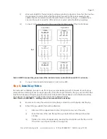
Wire motor leads for the appropriate voltage, referring to Figure 6. Note that the top four
diagrams are for U.S. motors, while the bottom two are for CE motors, usually for use
outside the U.S. Be certain to wire the motor for the correct voltage — a mistake here
can ruin the motor and/or the VFD and is not covered under the factory warranty.
G)
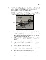
Connect motor ground wire to the ground bar located inside of the Control Panel.
Note: ALWAYS connect the ground wire of the included motor cable at both ends, MCP and motor.
H)
Connect motor leads to terminals U, V, & W on the VFD.
Step 8,
Install Guy Wires
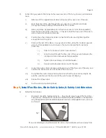
If an extension is installed, be sure to use the longer guy wires packaged with it. Be sure to use four guy
wires, with two clamps per end (four per guy wire). Keep the angle formed by the guy wire and the floor
less than 45 degrees. If longer guy wire is required, it is available inexpensively at most hardware stores.
Eye bolts are recommended to attach the wires to the building structure.
Note: This step is REQUIRED — omitting it may void manufacturer’s warranty!
A)
Be sure not to wrap the wire around any sharp corners to avoid fatiguing and fraying.
B)
Attach the guy wires to the building structure.
i)
Slide two of the supplied small cable clamps over one end of the wire.
ii)
Feed that end of the wire through the eye bolt and back through the cable
clamps.
iii)
Tighten the cable clamps securely, keeping the u-bolt side over the free end of
the cable — see figure 4 (in step 3 on page 12).
Fig 6


