- 1 -
Welcome
: Thank you for your purchase of the DWM-4 Digital Wattmeter. The DWM-4 represents
an advancement in technology that has never before been available in RF power measurement.
With the integration of a microprocessor to existing RF sensor technology, the DWM-4 offers the
flexibility of digital processing while keeping the interface to the user simple and straightforward.
Introduction:
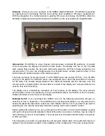
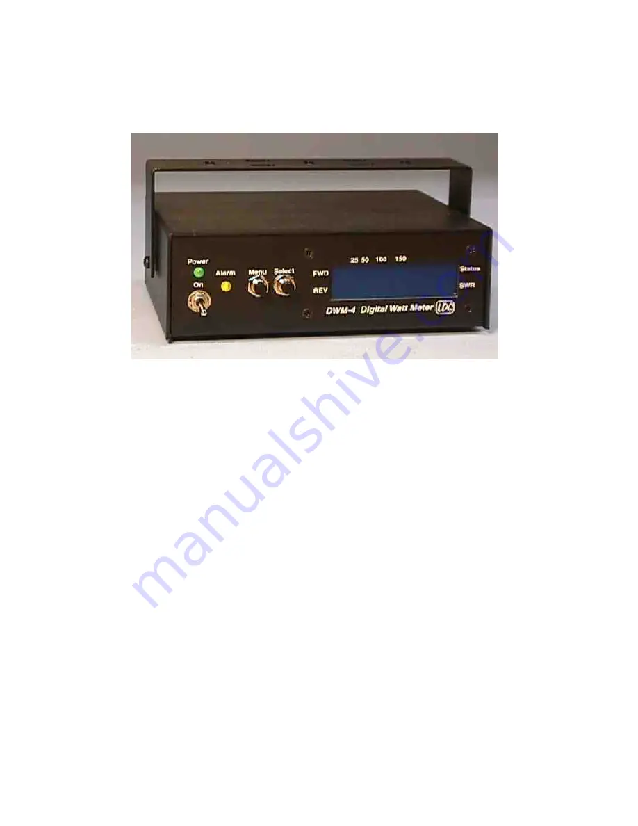
The DWM-4 is a four channel, microprocessor controlled RF wattmeter. It consists
of two main parts, the display unit and the remote sensor. The display unit has a 2 by 16 backlit
LCD module that provides the user with information about the RF that is being sampled by the
remote sensor. The user can simultaneously view forward power, reverse power and swr on the
same display for instant analysis of the antenna system.
There are two types of remote sensors. The HF/QRP sensor can sample RF from 1.8 to 54 MHz
and up to 150 watts. The VHF/UHF sensor can sample RF from 140 to 160 and 420 to 470 and up
to 150 watts. The modular design allows for the maximum flexibility with the minimum cost. The
remote sensor is supplied with a six-foot cable to connect to the display unit. A longer cable can be
used for truly remote sensing.
The display unit is controlled by a selection of menu screens on the display. The menu screens
and the data on them are selected by the two pushbuttons (Menu and Select) on the front panel.
Status information is also shown on the display.
Building the Kit:
If you purchased the DWM-4 as a kit, the following instructions will give an
overview of how to assemble it. If the DWM-4 was purchased assembled, you may still want to
review the assembly instructions to become more familiar with the unit. If you want to get right to
operating the unit, skip the assembly instructions and go right to the operation section.
Before getting the soldering iron out, go through all of the parts in the kit and familiarize yourself
with each component and its placement. Most of the parts are common, but there may be a few of
them that may be new to some builders. There are just over 100 parts and 200 solder connections,
so take your time.
The instructions are written to assemble the unit using the height order of the parts form lowest to
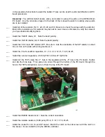
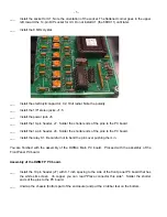
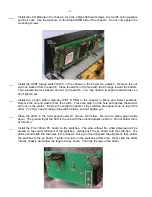
highest. This will assist the builder in the installation of the components. There are various photos

