background image

- 11 -

At a minimum, a 100 W HF radio and good 50ohm dummy load can be used to calibrate the HF
sensor and display unit. Even if you know how much power your radio emits, consider using an
additional wattmeter of known accuracy to assist you during the calibration process.

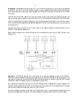
Start by setting R1 through R8 to their center positions. Connect the HF sensor to INPUT 1 on the
main board. Attach a voltmeter between ground and the reverse test point of the HF sensor. Apply
100 W through the HF sensor to a dummy load or resonant antenna; adjust C1 in the HF sensor for
minimum voltage. The minimum reading should be just about 0 Volts. A reading of 0.1 Volt or less
is fine. Be sure the pot for the reverse channel is centered for this adjustment. It is possible to get a
0 Volt reading if the pot is not set correctly.

Again apply 100 W and adjust R1 on the main board so that the forward display reads 100 W. Set
the LCD to display numbers instead of the bargraph. Swap the input and output leads of the HF
sensor and again apply 100 W. Adjust R2 to read 100 W on the reverse display. An error message
(REV>FWD) will appear, but the display is still visible between error-message flashes.

For VHF and UHF, connect a VHF/UHF sensor to one of the other channels. Apply RF power and
adjust the corresponding variable resistor to obtain a correct forward power display. Swap the input
and output leads and repeat for the procedure for reverse power. Repeat the foregoing process for
the other channels by connecting the appropriate sensor to each input and adjusting the
corresponding variable resistors.

Remote Operation

: The display head is designed to mount at the station transmitter. The display

unit can be used as table top or under shelf by using the mounting bracket. The mounting bracket
can also be used in a mobile installation.

The remote sensor is supplied with a six-foot cable. The sensor is usually mounted near the
transmitter, but it is possible to mount the remote sensor at the antenna for remote sensing. Be
sure to note that when mounting the sensor at the antenna, the use of an antenna tuner will not
produce the proper readings.

For remote sensing at long distances, a three wire shielded cable must be used. The wire must be
#20 or larger to prevent voltage loss with distances over 100 feet.

Accuracy—a Virtual Bird:

 The accuracy of the DWM-4 is directly related to its calibration. If you

have an accurate wattmeter or RF power source to which to compare it, the accuracy of the DWM-
4 will be correspondingly precise. The displayed values are derived from a huge look-up table
stored in the microprocessor. These table values were taken from the readings of a Bird 43A
wattmeter. The table was derived by comparing the A/D reading supplied by the HF and VHF/UHF
sensors for various RF readings on the Bird meter. The Bird readings were then graphed and
extrapolated where needed to fill in the gaps.

The resolution of the DWM-4 is about 1 W on the 150 W scale and 0.1 on the 15 watt scale.

 Even though the overall accuracy as compared to a Bird wattmeter is better than 0.1%, the actual
accuracy still depends on the calibration.

Trouble Shooting:

 If there are any problems, first check all components for proper value,

placement and polarity. Next look at the solder connections. Check for cold solder joints and solder
bridges first, since they are the number one cause of problems with the kits.

Does nothing: Check for 12 volts getting to PC board (be sure the switch is on). Check for 5.0 volts
out of 7805 (the left pin). Make sure the 10-pin ribbon cable is installed. Make sure the socket for U1

Summary of Contents for Digital Wattmeter DWM-4

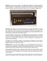
Page 1: ... minimum cost The remote sensor is supplied with a six foot cable to connect to the display unit A longer cable can be used for truly remote sensing The display unit is controlled by a selection of menu screens on the display The menu screens and the data on them are selected by the two pushbuttons Menu and Select on the front panel Status information is also shown on the display Building the Kit ...

Page 2: ...e the band polarity ___ Install the 10K 10 pin SIP resistor RP1 Be sure to note the orientation of the SIP resistor A small line or dot on the side with writing marks pin 1 ___ Install the 01uf monolithic capacitors C1 3 5 7 10 12 15 17 20 22 25 ___ Install the ceramic capacitors C6 100pf 1KV C26 27 10pf 500v ___ Install U2 the 7805 Align the 2 hole in the regulator with the 2 hole in the PC board...

Page 3: ...C board ___ Install the 14 pin header J8 Solder the shorter ends of the pins to the PC board ___ Install the relay K1 Be careful not to bend the pins over pushing them in You are finished with the assembly of the DWM 4 Main PC board Proceed with the assembly of the Front Panel PC board Assembly of the DWM FP PC board ___ Install the 10 pin header J7 with 0 1 inch spacing to the side of the front p...

Page 4: ...the hole and replace the washer and nut on the switch Be sure the solder terminals of the switches are aligned one on top of the other You may need to realign the switches later so don t tighten yet ___ Place the LEDs in the front panel board D1 Green D2 Yellow Be sure to place ground side down The ground leg of the LED is the one with the notched plastic next to it Do not solder them at this time...

Page 5: ...uld match the socket ___ Install U3 the LM339 by carefully pressing it into place in its socket Note that U3 has a notch that should match the socket ___ Install the ribbon cable with the red stripe connecting pin 1 of J7 to pin 1 of J7 2 x 7 header on the front panel ___ Install the ribbon cable with the red stripe connecting pin 1 of J8 to pin 1 of the LCD Module on the front panel VHF UHF Remot...

Page 6: ...t this time ___ Place the PC board onto the SO 239s Align the 1 8 jack with the hole in the enclosure Once this is in place you may tighten the nuts that are underneath the PC board You do this by pressing the board down on the nuts while turning the screw Repeat with the other three screws ___ Install the remaining four nuts on top of the PC board and tighten ___ Solder the SO 239s to the PC boar...

Page 7: ...te you must wind this in the direction shown in figure 2 ___ After scraping the insulation from the ends of all four wires connect the green 2 wire to the red 1 wire and twist together You will now have three leads the red wire on the left the twisted pair and the green wire on the right Do not install T1 yet ___ Install all of the resistors R1 2 3 and 4 ___ Install the 1N4148 diodes D1 and D2 Not...

Page 8: ...ncluded in the kit to the PC board in the hole to the left of T1 Place the other end through the center of T1 and solder to the bottom of the PC board ___ Install 1 8 stereo jack ___ Unwrap the enclosure Install the SO 239 connectors Put one 4 screw in hole and place two nuts on the screw Do not tighten them at this time ___ Place the PC board onto the SO 239s Align the 1 8 jack with the hole in t...

Page 9: ...mote sensor Connect the other end to input 1 on the DWM 4 display unit Other remote sensors for a total of four can be connected the same way to other inputs on the display unit Operation Turning the display unit on will show the model and software version of the DWM 4 The power LED is software controlled so it will only come on if the software is running properly You may have to adjust the contra...

Page 10: ... and holding the Select button turns on the alarm and counts from 1 1 to 30 0 for the alarm threshold Pressing the Select button again turns off the alarm The RELAY THRESHOLD menu is separate from the ALARM THRESHOLD The Select button works as it does with the ALARM THRESHOLD but only controls the operation of the relay K1 The RELAY RESET menu chooses between MANUAL and AUTO reset In MANUAL reset ...

Page 11: ...ed as table top or under shelf by using the mounting bracket The mounting bracket can also be used in a mobile installation The remote sensor is supplied with a six foot cable The sensor is usually mounted near the transmitter but it is possible to mount the remote sensor at the antenna for remote sensing Be sure to note that when mounting the sensor at the antenna the use of an antenna tuner will...

Page 12: ...ered with acid core We reserve the right to refuse repair due to excessive problems or damage due to construction Before any unit is sent to us you must first call or e mail to get return authorization All units sent back must be prepaid either by check money order or Credit Card unless other arrangements are made Package the unit carefully and keep in mind that we will use your packaging to retur...

Reviews: