

1 www.macurco.com
Rev: 2/06
MACURCO GAS DETECTORS
DMK-1
INSTALLATION
AND OPERATION INSTRUCTIONS
WWW.MACURCO.COM
GENERAL INFORMATION
The DMK-1 is a duct mount enclosure that provides the means to duct mount all of Macurco’s
standard 4 x 4 mount gas detectors. By duct mounting a gas detector, the unit is able to monitor gas
concentrations in ventilation ducts.
THE FOLLOWING PARTS ARE INCLUDED WITH THE DMK-1:
Enclosure
with
cover
and
gasket
1
EMT Setscrew Adapter
2
¼” X
≈
6”
Exhaust
Tube
1
¼” X 1.1” hex aluminum
spacers
4
Machine Screws 4/40 x ½” phillips flat head
4
Machine Screws 4/40 x 3/8” phillips pan head
4
Strain relief / seal for wiring exit hole
1
Nut
for
strain
relief 1
Sheet metal mounting screws #6 X 1”
4
Adhesive
foam
compression
seal
2
A
full
size
drill
template
1
1/2” sampling tube (outer diameter)
not provided
0
INSTALLATION
1. Open the enclosure by removing the 4 black integrated cover screws.
2. Install the setscrew adapters into the 2 (entrance and exit) holes drilled into the back of the enclosure
so that the setscrew side of the adapter is on the outside of the enclosure.
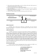
3. Decide which hole will be used for sampling and which will be used for exhaust. The sampling tube
(
not provided
) should be on the ”upstream” side of the enclosure, as it is to be mounted on the duct
(“upstream” refers to the flow of air in the duct * see
reference diagram
below*).
4. Install the exhaust tube into one of the setscrew adapters so that the squared end is mated to the
setscrew adapter and the pointed end is toward the duct. The tube should be turned so that the longer
pointed side is facing the direction of “upstream” air flow.
5. Install the sampling tube (
not provided
) into the other setscrew adapter according to the sampling tube
manufacturer’s instructions.
6. Install the detector onto the top of the 4 hex aluminum spacers. Secure it in place using the 4 pan head
machine screws. Run the wiring through the strain relief. Twist the outer cap of the strain relief
clockwise to compress the gasket material around the wiring.
7. Mark and drill the 2 large (1 ½”) and 4 small (3/32) holes in the duct you want to mount the unit on,
using the template provided. The two large holes are for the sampling and exhaust tubes. The four
small holes are starter holes for the sheet metal mounting screws. Ensure that the sampling and exhaust
tube holes are large enough to allow the setscrew adapters to fit.


