MACHINE
SCREW
CAUTION:
Check that the installed product will have sufficient clearance and wiring
room prior to installing back boxes and conduit.
CAUTION:
Do not over tighten mounting screws.
Excessive torque can distort the base
and may affect operation.
CAUTION:
When using power tools to screw down the mounting plate to the electrical back
box, ensure the torque is set to the lowest setting
available.
Figure 4: Standalone Detector
5 / 8
MOUNTING OPTIONS
NOTE:
1. Connect field wiring to contacts on back of device.
2. Dress wires back into back box.
3.
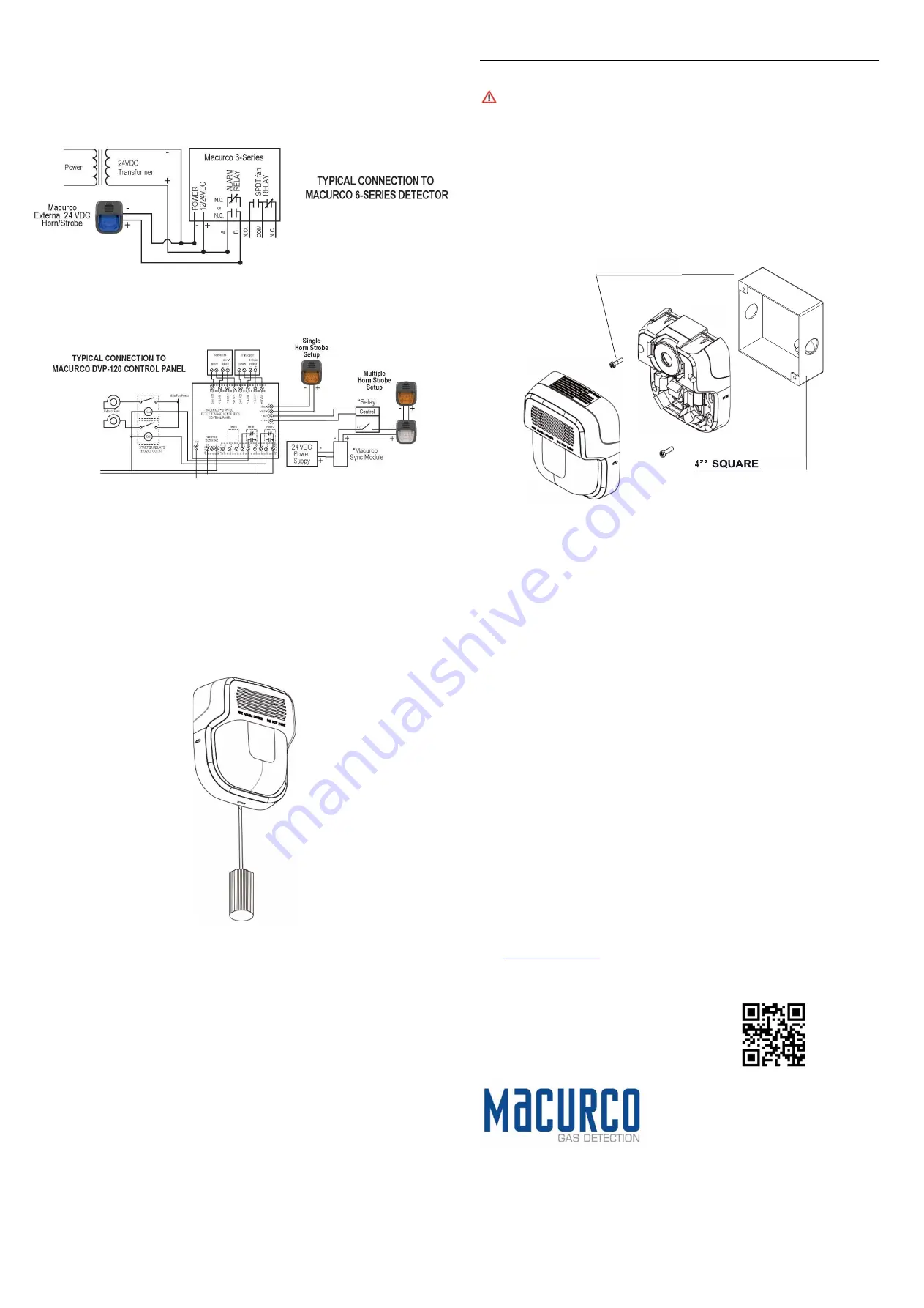
Install device as shown in Figure 6 to a standard 4" x 4" x 1 1/2" back box with the provided
pan head screws.
4. Snap warning cover over device.
NOTE: Back box must be recessed flush with the wall surface.
IMPORTANT: Device only has one mounting orientation.
LED light element should be pointed
towards ground.
5. To remove the appliance, insert a small flat-bladed screwdriver into the bottom opening ½”
as shown in Figure 7.
Then pry off cover with the screwdriver and then unscrew device.
WARNING: DO NOT paint this device.
Figure 6:
4-Inch Square Back Box Installation
6 / 8
Figure 7.
Cover Removal
NOTE:
Back box must be recessed flush with the wall surface.
IMPORTANT: Device only has one mounting orientation. LED light element should be pointed towards
ground.
WARNING: When installing strobes in an open office or other areas containing partitions or other
viewing obstructions, special attention should be given to the location of the strobes so that their
operating effect can be seen by all intended viewers, with the intensity, number, and type of strobes
being sufficient to make sure that the intended viewer is alerted by proper illumination, regardless of
the viewer’s orientation.
WARNING: A small possibility exists that the use of multiple strobes within a person’s field of view,
under certain circumstances, might induce a photo-sensitive response in persons with epilepsy. Strobe
reflections in a glass or mirrored surface might also induce such a response. To minimize this possible
hazard, it is strongly recommended that the strobes installed should not present a composite flash rate
in the field of view which exceeds five (5) Hz at the operating voltage of the strobes.
It is also strongly recommended that the intensity and composite flash rate of installed strobe and horn
comply with levels established by applicable laws, standards, regulations, codes and guidelines.
Macurco Gas Detection
1504 W 51
st
St.
Sioux Falls, SD 57105
Technical Support Contact Information
Phone:
1-844-325-3050
Fax:
1-605-951-9616
Email:
support@macurco.com
Website:
macurco.com/service/
REV – 1.0.0
Issue Date: 03-15-2023
Document No: 34-1221-4100-3
© Macurco 2023. All rights reserved.
Macurco is a trademark of Macurco, Inc.
7 / 8 8 / 8
General Contact Information
Phone :
1-877-367-7891
Fax :
1-605-951-9616
Email:
info@macurco.com
Website:
www.macurco.com
Figure 5: System Diagram with
Sync Module


